Nullam dignissim, ante scelerisque the is euismod fermentum odio sem semper the is erat, a feugiat leo urna eget eros. Duis Aenean a imperdiet risus.
Nullam dignissim, ante scelerisque the is euismod fermentum odio sem semper the is erat, a feugiat leo urna eget eros. Duis Aenean a imperdiet risus.
 author
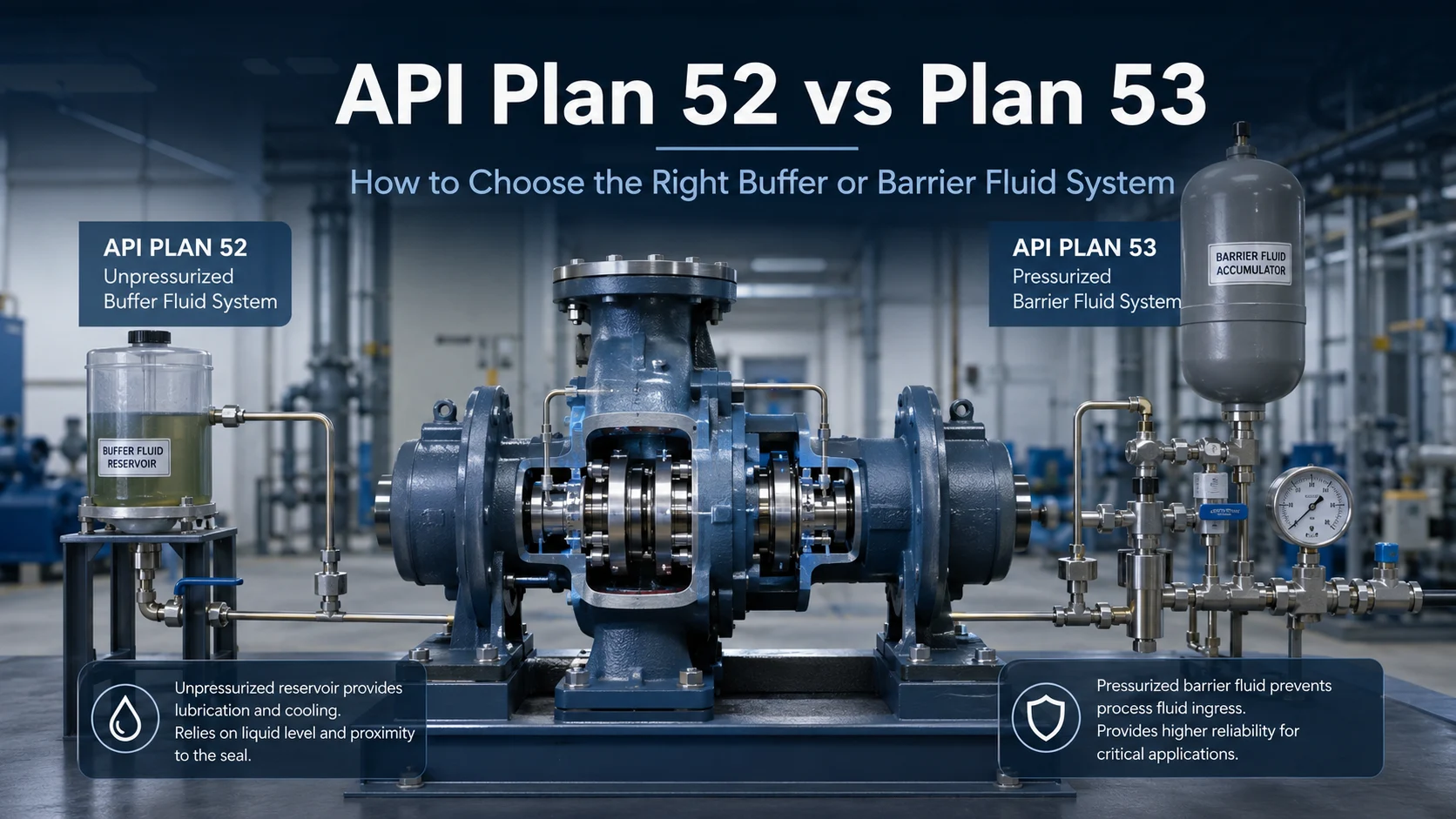
Choosing between API Plan 52 and Plan 53 is not simply a matter of deciding whether a dual mechanical seal needs an auxiliary fluid. The real decision is whether the application can operate with an unpressurized buffer-fluid system or requires a pressurized barrier-fluid system to control the direction of leakage. For engineers and procurement teams, that choice affects process containment, contamination risk, utilities, monitoring, maintenance, and the specification of the complete seal support system.
API Standard 682 covers shaft sealing systems for centrifugal and rotary pumps, while its piping-plan framework supports different seal arrangements and operating requirements. For buyers reviewing complete sealing solutions, Xinyoumi mechanical seal solutions include pump seals, reactor seals, and sealing auxiliary systems for industrial applications.
Plan 52 provides buffer fluid to an unpressurized dual seal arrangement. Plan 53 uses pressurized barrier fluid for a pressurized dual seal arrangement. The pressure relationship changes what happens when fluid crosses the inboard seal and is therefore central to the selection decision.
| Decision Factor | API Plan 52 | API Plan 53 |
|---|---|---|
| Typical dual-seal arrangement | Arrangement 2 | Arrangement 3 |
| Support fluid | Buffer fluid | Barrier fluid |
| Support-fluid pressure | Below seal-chamber pressure | Above seal-chamber pressure |
| Leakage behavior | Process fluid can enter the buffer system | Barrier fluid tends to enter the process |
| Main selection concern | Can process leakage be safely contained? | Is higher containment required? |
| Process contamination concern | Lower risk from support-fluid ingress | Barrier-fluid compatibility must be reviewed |
| Pressure source | No pressurized barrier required | A suitable pressurization method is required |
| System complexity | Generally simpler | Requires pressure control and monitoring |
| Next selection step | Confirm Plan 52 suitability | Select the appropriate Plan 53 configuration |
This comparison should be treated as a first-stage screening tool rather than a final specification. Process fluid, seal-chamber pressure, temperature, emissions requirements, acceptable contamination, utilities, and seal design must still be reviewed before equipment is selected.
The terms “buffer fluid” and “barrier fluid” are sometimes treated as if they simply describe different liquids. For Plan 52 vs Plan 53 mechanical seal selection, the more important distinction is pressure.
In Plan 52, the buffer system is unpressurized relative to the process. Plan 52 commonly uses an external reservoir, with circulation generated by the seal system, such as through a pumping ring. In Plan 53, the barrier fluid is maintained above seal-chamber pressure so that the pressure relationship changes the preferred leakage direction.
API Plan 52 can make sense when a dual unpressurized seal is suitable and limited process leakage into the buffer system can be safely managed. It is commonly considered when process fluid crossing the inboard seal can be collected or handled and when the plant has an appropriate vent or recovery arrangement.
The important question is therefore not simply, “Is Plan 52 cheaper or simpler?” Engineers should ask what happens after the inboard seal begins to leak. If the medium enters the buffer fluid, can the system tolerate the resulting contamination, pressure change, vapor generation, or fluid-property change? If the process is hazardous or containment requirements are strict, those consequences may make an unpressurized arrangement unsuitable.
Plan 53 uses a pressurized barrier-fluid system for a pressurized dual mechanical seal arrangement. Because barrier pressure is maintained above seal-chamber pressure, controlled leakage tends to move from the barrier side toward the process rather than allowing process fluid to migrate outward through the inboard seal.
That arrangement can be valuable where process containment is a major concern, but it creates another selection requirement: the barrier fluid must be evaluated for compatibility with the process. If small amounts of barrier fluid entering the product could cause unacceptable contamination, a Plan 53 system cannot be specified solely on the basis of containment. The seal design, pressure margin, barrier fluid, process requirements, and operating conditions must be evaluated together.
Plan 52 should be considered when an Arrangement 2 sealing philosophy meets the plant’s containment requirements and process fluid entering the buffer system can be managed safely. It may also be relevant where support-fluid ingress into the process is undesirable and the process itself does not justify a pressurized barrier arrangement.
Selection should begin with the consequence of inboard-seal leakage. Confirm whether the process medium can enter the buffer system without creating an unacceptable safety, environmental, maintenance, or operating problem. Also review whether vaporized leakage can be handled by the available vent or collection arrangement, which is one of the operating considerations associated with Plan 52.
For procurement, the required information includes medium properties, normal and maximum seal-chamber pressure, temperature, vapor behavior, leakage tolerance, and available plant connections. Dirty, crystallizing, polymerizing, or otherwise difficult fluids may require additional engineering review rather than automatic selection by plan number.
System complexity and purchase price matter, but they should follow the process-risk decision rather than determine it.
A Plan 52 system that does not match the containment requirement can lead to repeated alarms, contaminated buffer fluid, excessive venting, or recurring seal problems. If an existing Plan 52 arrangement has persistent leakage or the process conditions have changed, review the seal arrangement and support-system philosophy before replacing the reservoir or mechanical seal with the same configuration.
A Plan 53 barrier-fluid system becomes more relevant when preventing process leakage toward the atmosphere or secondary containment system is a higher priority. Typical decision factors include process hazard, emissions requirements, pressure, temperature, and the consequences of seal failure.
Hazardous, toxic, flammable, volatile, or emissions-sensitive services may justify evaluating a pressurized barrier system, but process classification alone should not dictate the final plan. Engineers must also determine whether barrier-fluid ingress into the process is acceptable and whether the required pressure relationship can be maintained throughout startup, normal operation, shutdown, and process upset conditions.
If Plan 53 is selected, barrier-fluid compatibility becomes a procurement requirement. The fluid should be assessed against process chemistry, temperature, seal materials, and product-contamination limits rather than selected from a generic list.
“Plan 53” is not a complete equipment specification. Plan 53A, 53B, and 53C use different methods to establish or follow barrier pressure. Current API piping-plan references distinguish a gas-pressurized reservoir for Plan 53A, a bladder accumulator for Plan 53B, and a piston accumulator for Plan 53C.
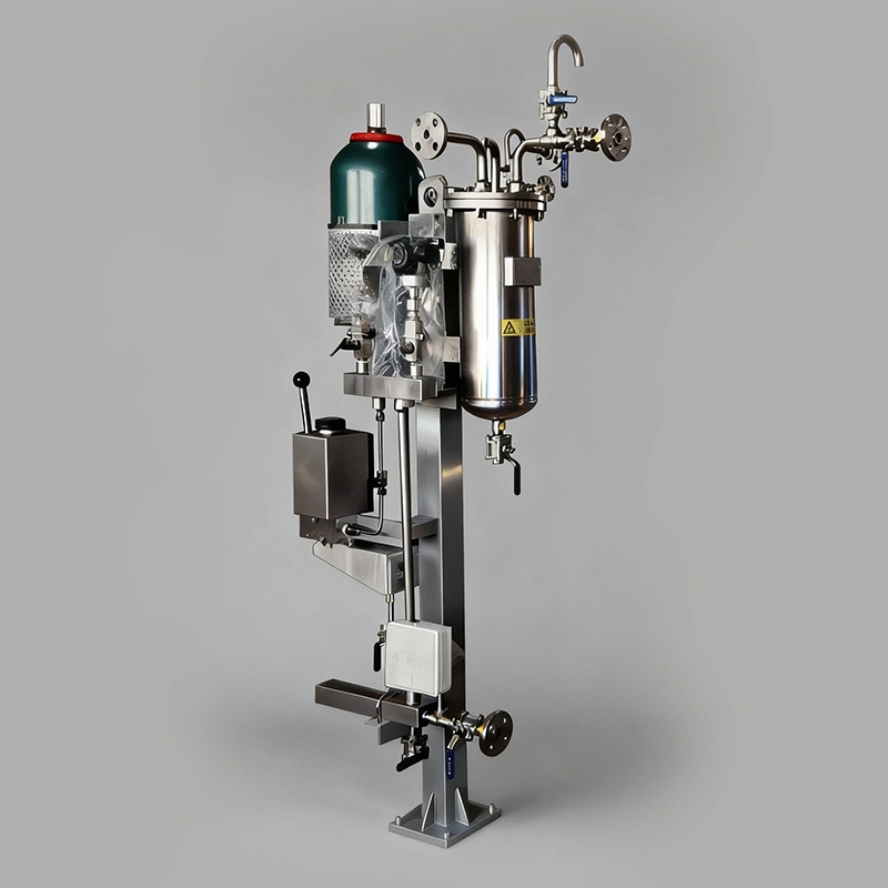
Once a pressurized barrier philosophy has been selected, pressure stability, nitrogen availability, seal-chamber pressure variation, temperature, heat removal, instrumentation, and maintenance practices determine the next choice. For that second-stage decision, see Plan 53A vs Plan 53B vs Plan 53C rather than trying to solve both selection levels in one step.
A dual mechanical seal can still leak or suffer short service life when the support system is incorrectly selected, commissioned, or maintained. The plan number alone cannot compensate for incorrect pressure, poor circulation, incompatible fluid, or process conditions outside the original design basis.
For Plan 53, failure to maintain the intended barrier pressure can change the system’s leakage behavior. Pressure source, instruments, piping, accumulator or reservoir condition, and fluid level therefore need to be included in troubleshooting.
For either Plan 52 or Plan 53, poor fluid circulation can also increase temperature around the seal faces. When unexplained temperature rise, repeated level changes, abnormal pressure behavior, or seal leakage appears, maintenance teams should verify both the mechanical seal and the support circuit instead of replacing only the seal faces.
Support-fluid selection should account for process chemistry, temperature, lubrication characteristics, and potential interaction with seal materials. With Plan 52, process leakage may alter the properties of the buffer fluid. With Plan 53, barrier-fluid ingress may affect the process.
Before specifying a fluid, confirm what happens in both directions of possible leakage. A fluid that is suitable for the seal faces may still be unacceptable for the process, and a process-compatible liquid may not provide suitable lubrication or temperature performance for the seal.
A Plan 52-to-Plan 53 retrofit should be treated as a review of the mechanical seal and support system together, not simply as a matter of pressurizing an existing vessel.
First confirm whether the existing mechanical seal arrangement is suitable for pressurized barrier operation. Then document minimum, normal, and maximum seal-chamber pressure, operating temperature, shaft speed, process medium, acceptable contamination, available nitrogen or other utilities, cooling requirements, existing piping, instrumentation, and installation space.
The pressure source and support equipment must also match the actual duty. Depending on the process, an accumulator-based arrangement may be considered rather than a gas-pressurized reservoir. Xinyoumi publishes a Plan 53B seal support system with specified design conditions and accumulator precharge requirements; the exact configuration for a project should still be checked against submitted operating data and the applicable specification.
A useful quotation requires more than the pump model and the words “Plan 53.” Before requesting a dual mechanical seal support system, prepare the following information:
Buyers comparing available mechanical seal support systems should use this operating data to evaluate whether the proposed configuration reflects the real process rather than only matching a generic plan number. Xinyoumi’s product structure includes sealing auxiliary systems alongside pump and reactor mechanical seals.
The supplier-selection stage should test engineering discipline as much as manufacturing capability. A technically useful quotation should identify what process data were used, what remains to be confirmed, and why the proposed seal arrangement and support plan match the application.
A supplier should ask about pressure, temperature, medium, speed, leakage tolerance, utilities, existing equipment, and previous failures before finalizing the configuration. Material selection and auxiliary-system design should also be reviewed together because leakage, corrosion, temperature, vibration, and poor operating conditions can interact rather than occur as isolated problems.
Kunshan Xinyoumi Mechanical Seal Technology Co., Ltd. designs and supplies pump mechanical seals, reactor mechanical seals, and sealing auxiliary systems, with modular mechanical-seal designs included in its published product and company information. This makes the supplier evaluation most useful when the submitted RFQ includes both seal data and support-system requirements rather than requesting a vessel as a standalone component.
Before approving an order, verify the proposed plan, pressure and temperature design basis, wetted materials, reservoir or accumulator configuration, instrumentation, connections, cooling requirements, barrier or buffer fluid assumptions, drawings, spare-parts requirements, and commissioning instructions.
For example, the published Xinyoumi Plan 53B page specifies a bladder-based system with defined design pressure, temperature, precharge, pressure-testing, and preparation requirements. These values should not be assumed to fit every application; project requirements must be checked against the actual mechanical seal support system specification before purchase.
The API Plan 52 vs Plan 53 decision comes down to leakage philosophy and process consequences. Plan 52 uses an unpressurized buffer system where controlled process leakage can be managed. Plan 53 uses a pressurized barrier system when stronger process containment is required, while introducing the need to evaluate barrier-fluid ingress, pressure control, and support-system complexity.
For a new installation, retrofit, or repeated seal-failure investigation, purchasing decisions should be based on actual operating data rather than plan number alone. Xinyoumi can review submitted equipment information as part of seal and auxiliary-system selection. Buyers can contact Xinyoumi with the existing seal model, drawings, process medium, pressure range, temperature, speed, available utilities, failure photographs, and required quantity for technical review.
No. Plan 52 is an unpressurized buffer-fluid system used with a dual unpressurized seal arrangement. The buffer-fluid pressure remains below the process/seal-chamber pressure.
Yes. Because Plan 53 maintains the barrier fluid above seal-chamber pressure, some controlled barrier-fluid leakage toward the process can occur. This is why barrier-fluid compatibility and acceptable product contamination must be evaluated during selection.
It depends on the process risk, leakage consequences, plant containment system, and project requirements. A hazardous medium should not automatically be assigned to Plan 52 or Plan 53 based on fluid name alone. The consequences of process leakage and the required containment level should drive the decision.
No. Plan 53 provides a different containment philosophy, not a universal upgrade for every dual seal. If barrier-fluid ingress is unacceptable or a pressurized system adds unnecessary complexity for the application, Plan 52 may be more appropriate.
All three are pressurized barrier-fluid arrangements, but their pressurization methods differ. Plan 53A uses a pressurized reservoir, Plan 53B uses a bladder accumulator, and Plan 53C uses a piston accumulator that can follow changing seal-chamber pressure. The final choice depends on operating pressure, pressure variation, utilities, temperature, and project requirements.