Nullam dignissim, ante scelerisque the is euismod fermentum odio sem semper the is erat, a feugiat leo urna eget eros. Duis Aenean a imperdiet risus.
Nullam dignissim, ante scelerisque the is euismod fermentum odio sem semper the is erat, a feugiat leo urna eget eros. Duis Aenean a imperdiet risus.
 author
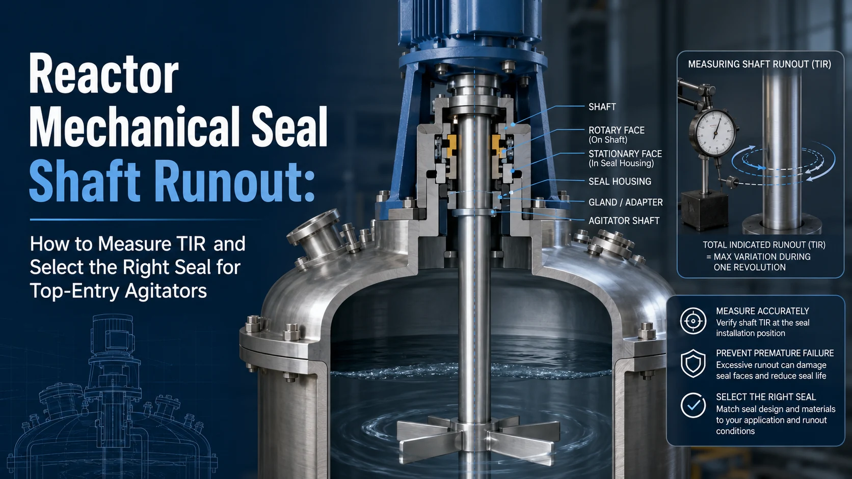
There is no universal reactor mechanical seal shaft runout limit. Allowable movement depends on the model, shaft diameter, speed, support, axial movement, and measurement method. A top-entry agitator may pass a stationary pressure test yet leak after startup because the long shaft bends or moves under operating load. Before ordering another seal, teams should measure total indicator reading, identify the source of movement, and compare it with a product-specific limit.
Published mixer-seal specifications show why one number cannot apply to every reactor. Depending on shaft size and design, official product pages publish capabilities ranging from about 1.14 or 1.52 mm TIR to more than 3 mm TIR. Designs may use increased clearances, flexible rotors, or bearing options. These figures describe particular products under stated operating limits; they are not a general tolerance for all top-entry agitators.
Confirm the model, shaft range, speed, pressure, temperature, lubrication mode, and axial or angular limits. A larger published TIR value is not automatically better if the configuration is unsuitable for the process or installation space.
Total indicator reading is the difference between the highest and lowest readings during a measurement cycle. It should not automatically be treated as one-sided centerline displacement. “Radial movement,” “runout,” “shaft deflection,” and “angular deflection” may also describe different conditions. Mitutoyo defines TIR as the absolute difference between maximum and minimum readings, while mixer-seal specifications may list radial, axial, and angular limits separately.
Ask what was measured, where, under which operating state, and for which shaft diameter and configuration.
Runout near the coupling may differ from movement at the seal location or farther down a long overhung shaft. For seal selection, provide a reading as close as practical to the sealing position and identify the reference surface. Mount a dial indicator on a stable structure, contact a clean shaft or sleeve, rotate one revolution, and record maximum and minimum readings. Dial indicators are commonly used to check runout, but repeatable mounting is essential.
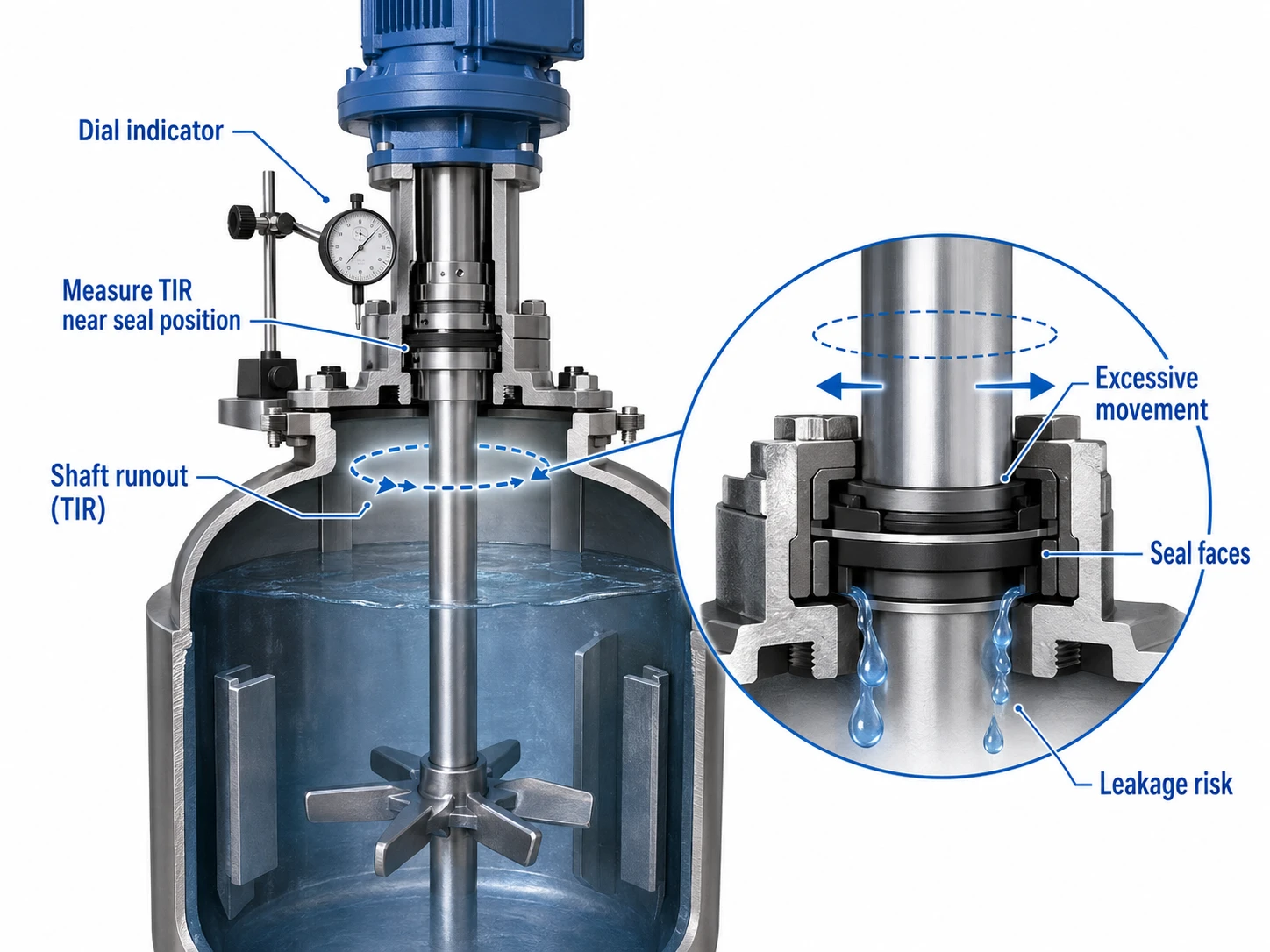
State the assembly condition and whether the vessel was empty or loaded. Static hand rotation identifies geometric eccentricity; it may not reproduce dynamic deflection caused by speed, product load, or a long cantilevered shaft.
Geometric runout appears as the shaft is slowly rotated. Dynamic deflection develops under operating load. Misalignment concerns the relationship between connected axes, while axial movement occurs along the shaft centerline. A reactor can have acceptable static TIR yet develop visible movement at operating speed.
Record radial TIR, axial endplay, speed, vibration, and changes with liquid level or viscosity. If leakage rises with speed or batch load, dynamic deflection or imbalance deserves attention. If axial wear marks appear, measure endplay rather than assuming every problem is radial.
A mechanical seal relies on controlled face contact and a stable lubricating film. Repeated radial movement can disturb face tracking and load secondary seals or flexible components unevenly. The result may be intermittent face opening, temperature rise, chipped edges, uneven wear tracks, or leakage only while the agitator turns.
If a static test passes but the seal leaks in operation, compare leakage with speed and product level. Inspect the old faces for localized contact, edge damage, heat marks, or a nonuniform wear band. Rule out misalignment, installation damage, unsuitable secondary seals, and poor lubrication before blaming runout.
A long shaft can move inherently, but increasing runout may indicate bearing wear, gearbox clearance, bending, coupling error, loose mounting, imbalance, or buildup. These conditions should not be hidden by repeatedly installing more tolerant seals.
| Symptom | Likely condition | Evidence to collect | First action |
|---|---|---|---|
| Static test passes; leakage starts when running | Dynamic shaft movement | TIR and leakage versus speed | Measure near the seal |
| Leakage rises with speed or batch load | Deflection or imbalance | Speed, level, and vibration trend | Inspect shaft and impeller |
| Runout increases over time | Bearing or gearbox wear | Maintenance history | Repair the drive |
| New seals fail in the same pattern | Selection or equipment mismatch | Failed parts and shaft data | Review the configuration |
| Axial wear marks appear | Excessive endplay | Axial movement | Inspect bearings and coupling |
Repair should come first when movement is increasing, bearings are loose, the gearbox is deteriorating, the shaft is bent, or mounting components are unstable. A high-runout seal can accommodate defined movement; it should not justify continued operation with a developing mechanical fault.
After repair, repeat the measurement at the same location and comparable conditions to confirm the correction.
A floating or flexible design may suit a long top-entry shaft with predictable radial movement. A bearing-supported seal may stabilize the shaft near the faces when local support is insufficient. Mixer seals may use flexible rotors, enlarged clearances, floating components, or steady bearings, each with different requirements.
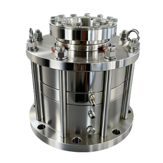
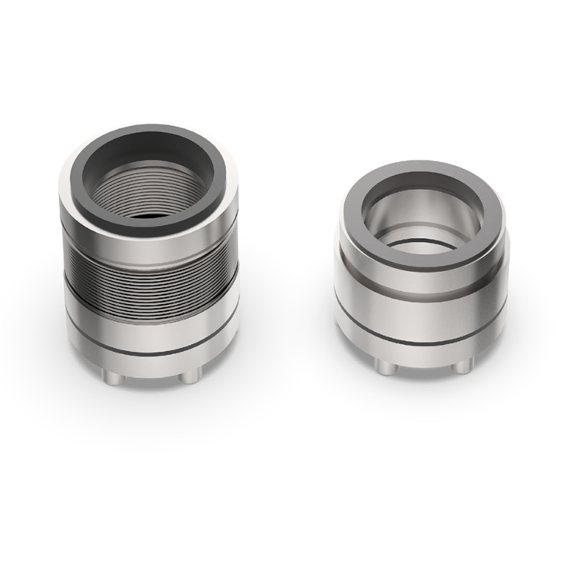
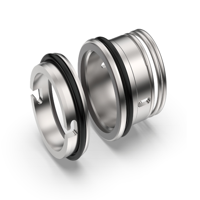
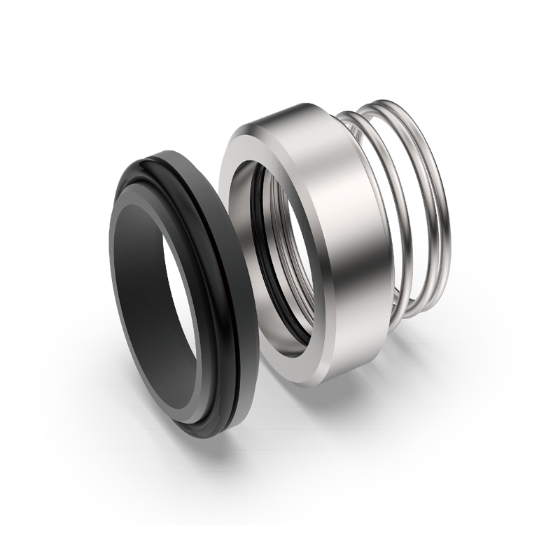
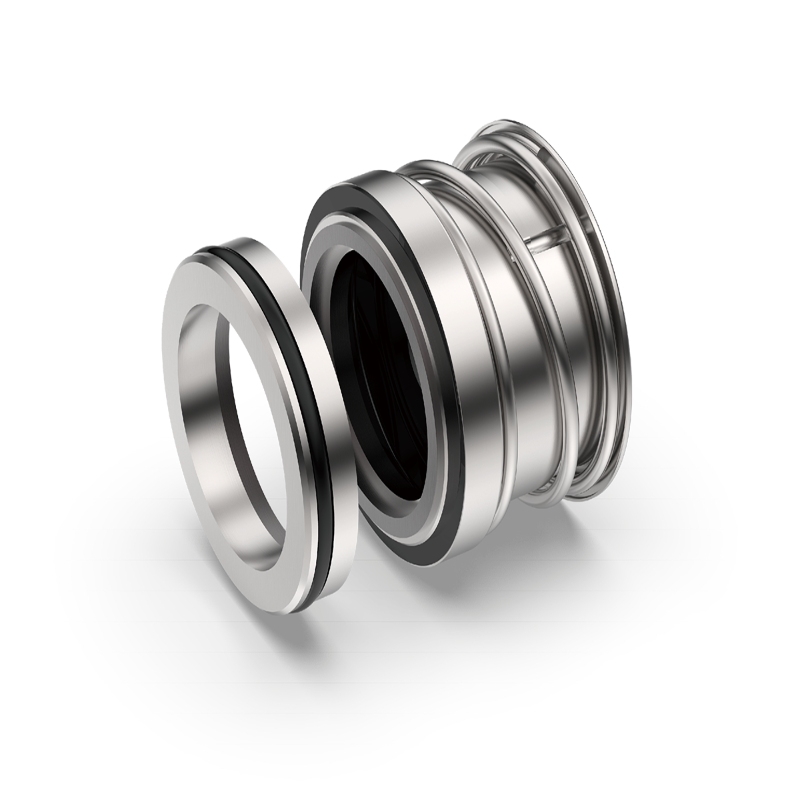
Buyers should compare reactor mechanical seal systems for shaft movement by measured TIR, axial movement, shaft size, speed, process pressure, available height, and bearing arrangement. Xinyoumi lists the J212S mechanical seal for large-runout rotating equipment for horizontal and vertical equipment with large runout, as well as high-temperature and dry-running conditions. The acceptable TIR and final configuration must still be confirmed for each application.
Older reactors may combine large runout with short space, poor shaft finish, or fixed dimensions. A custom cartridge, floating structure, or precision sleeve may then be considered after the drive system has been assessed.
Xinyoumi technical materials describe a customized retrofit approach for equipment with large radial runout, limited axial space, and poor shaft accuracy. This supports application-specific engineering but does not establish a public universal TIR rating.
A useful RFQ should include:
Do not send only the old model number. A replacement may fit the flange yet remain unsuitable for the actual shaft movement.
A qualified supplier should define the limit, measurement location, shaft size, speed, arrangement, and operating conditions. It should also ask about axial movement, bearings, gearbox condition, and installation space.
Kunshan Xinyoumi Mechanical Seal Technology Co., LTD supplies reactor seals, pump seals, and sealing auxiliary systems and uses modular structures across its published range. Its materials also describe application-specific solutions for shaft movement and nonstandard retrofit conditions. Buyers can review Xinyoumi mechanical seal solutions before deciding whether a standard reactor seal, the J212S application direction, or a custom assessment is appropriate.
Warning signs include undefined “large runout,” no measurement location, no radial/axial distinction, or promises to replace all drive repairs.
Reactor mechanical seal shaft runout should be measured and defined before products are compared. There is no universal allowable TIR for top-entry agitators. The decision may be repair, a floating seal, local bearing support, or a custom retrofit.
For an application review, submit measured TIR, location, shaft diameter, speed, overhung length, axial movement, drive arrangement, process conditions, installation drawing, quantity, and failure photographs. Buyers can request a shaft-runout seal review to confirm which additional measurements are needed.
There is no universal value. Use the limit confirmed for the specific seal model, shaft diameter, speed, arrangement, and measurement definition.
Measure as close as practical to the seal working position and state the reference surface. Additional readings near the coupling can help identify where movement originates.
Dynamic deflection, runout, vibration, or axial movement may disturb the faces only after rotation and process load begin. A stationary pressure test does not reproduce these movements.
It may stabilize the shaft near the seal, but it does not automatically correct a bent shaft, worn gearbox, loose mounting, imbalance, or every form of dynamic deflection.
Provide TIR conditions, shaft dimensions, speed, overhung length, axial movement, drive details, process conditions, installation dimensions, and failure photographs.