Nullam dignissim, ante scelerisque the is euismod fermentum odio sem semper the is erat, a feugiat leo urna eget eros. Duis Aenean a imperdiet risus.
Nullam dignissim, ante scelerisque the is euismod fermentum odio sem semper the is erat, a feugiat leo urna eget eros. Duis Aenean a imperdiet risus.
 author
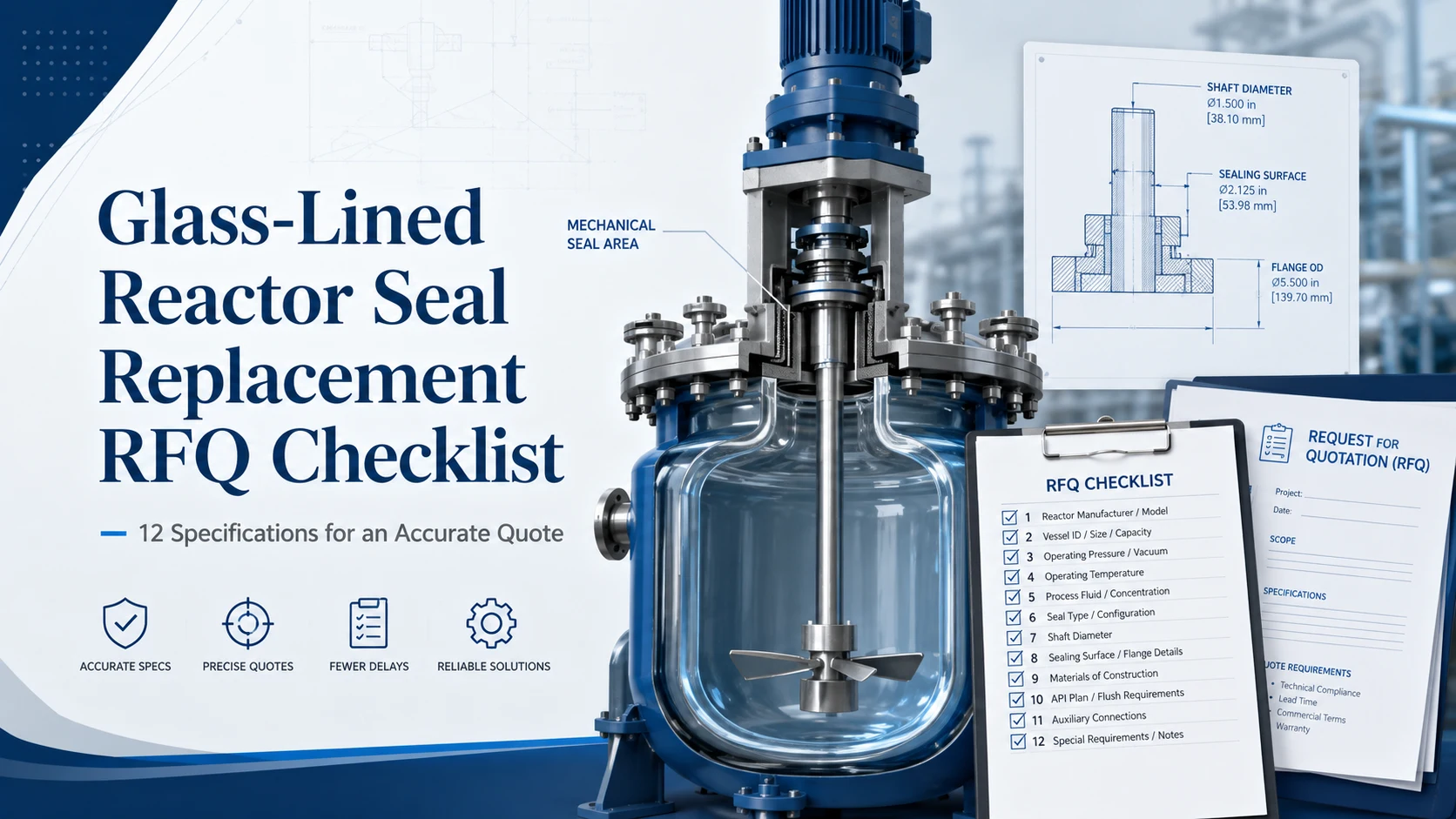
An accurate glass-lined reactor seal replacement quote requires more than an old model number, a shaft diameter, or several equipment photographs. The supplier must confirm whether the replacement fits the existing reactor interface, tolerates the complete operating cycle, remains compatible with the process medium, and meets leakage or contamination restrictions.
The following 12 specifications form a practical RFQ checklist for purchasing teams, maintenance engineers, reactor manufacturers, and plant operators. Each item should be measured or verified wherever possible. Unknown information should be marked as unknown rather than replaced with an unverified estimate.
A seal can match the shaft and flange yet remain unsuitable for the application. Shaft diameter, bolt pattern, and installation height determine whether the assembly can be installed. Pressure, vacuum, temperature, speed, shaft movement, medium, and leakage tolerance determine whether it can operate as intended.
This distinction matters because glass-lined reactors may use different nozzle standards, support arrangements, drive frames, and sealing configurations. Xinyoumi’s reactor product category includes several series for glass-lined, steel, and special-material reactors, so buyers should review the available glass-lined reactor mechanical seal systems rather than assume that every unit with the same nominal shaft diameter is interchangeable.
A direct replacement may be practical when the existing drawing is complete, the equipment has not been modified, the old seal performed acceptably, and current process conditions match the original duty.
A custom review becomes more appropriate when:
In these situations, the supplier may issue a preliminary budgetary quote before dimensional verification. A final manufacturing proposal should normally follow confirmed measurements and drawing approval.
The first four specifications establish what equipment is installed and whether a proposed replacement can physically fit.
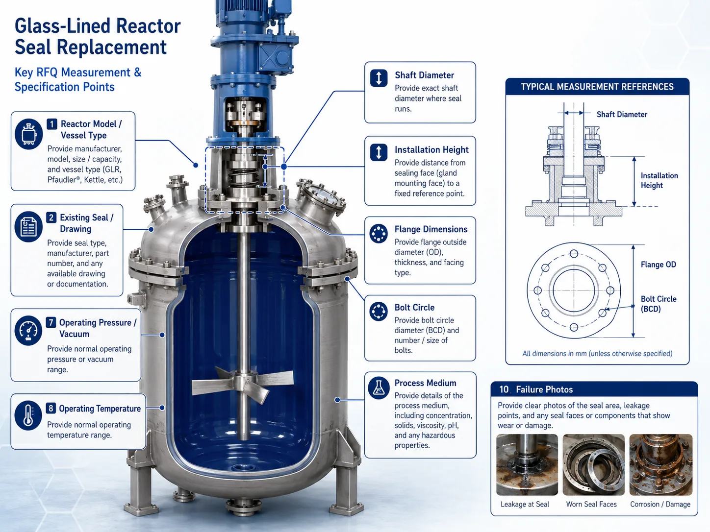
Provide the reactor manufacturer, equipment model, vessel capacity if known, entry position, and whether the vessel is glass-lined, steel, or made from another material. Include the reactor nameplate photograph.
This information helps the supplier identify the likely vessel-nozzle standard and installation arrangement. It should not replace direct measurement, especially on older equipment or reactors that have been repaired or modified.
Send the complete model number, nameplate, assembly drawing, previous purchase record, and photographs of the installed seal. Useful photographs include:
A model number can guide the review, but it does not confirm that the old seal was correctly selected or that current conditions remain unchanged.
Measure the shaft at the actual sealing and sleeve-contact positions. Record every step, shoulder, thread, keyway, and transition that may affect installation. Avoid measuring only a worn or corroded section.
Installation height should be measured from a clearly identified mounting datum to the relevant shaft shoulder, drive connection, or available upper boundary. Mark the same reference points on a sketch or photograph.
Provide the mounting-flange outside diameter, inside opening, raised or recessed features, bolt-hole diameter, number of holes, and bolt-circle diameter. Do not report an adjacent-hole distance as the bolt circle unless the calculation has been verified.
| Measurement | Recommended reference | Common error | Verification |
|---|---|---|---|
| Shaft diameter | Seal working position | Measuring only a worn section | Check several positions |
| Installation height | Defined mounting face | Using an unclear vessel-cover datum | Mark the datum on a sketch |
| Bolt circle | Circle through hole centers | Reporting adjacent-hole spacing | Confirm hole count and circle |
| Available space | Flange to drive or frame | Ignoring removal clearance | Record axial and radial space |
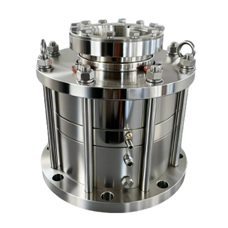
The 2020B/2020W reactor seal installation dimensions illustrate why a quotation may require the applicable reactor-nozzle standard, several flange diameters, bolt information, shaft diameter, and installation height. The platform is published for glass-lined, steel, and special-material reactors, but final suitability still depends on the submitted application data.
Static dimensions establish fit. Dynamic data establish whether the seal can follow the agitator shaft and withstand the real process cycle.
Provide normal and maximum shaft speed, rotation direction, radial runout, axial endplay, and any visible vibration. State where and how each value was measured.
Runout near the coupling may differ from movement near the seal. For replacement selection, the supplier needs data that represents the shaft behavior at or near the sealing position. If dynamic values are unavailable, mark them as not measured and describe whether leakage changes with speed, vessel level, or product viscosity.
Repeated leakage can originate from bearings, the gearbox, alignment, shaft deflection, or an unsuitable seal arrangement. A replacement should not be expected to conceal a developing equipment fault.
State:
“Negative pressure” is not sufficiently precise. The supplier should know whether the reactor holds a mild vacuum, reaches full vacuum, or repeatedly changes between vacuum and positive pressure.
Provide the normal process temperature, minimum and maximum temperature, cleaning temperature, sterilization temperature, and any rapid heating or cooling stages.
A single average temperature can hide the condition most likely to damage secondary seals, change material behavior, or cause crystallization. Temperature should be reported as a cycle rather than one isolated value when the reactor operates in batches.
These specifications help the supplier evaluate materials, seal arrangement, and auxiliary-system requirements.
A description such as “acid,” “solvent,” or “chemical liquid” is too broad. Provide:
When the full formula is confidential, provide sufficient chemical compatibility, physical-property, and hazard information for material evaluation.
Mechanical-seal structure and material selection should be matched to the equipment, pressure, temperature, corrosion, and particle conditions rather than treated as universal choices.
Explain whether atmospheric leakage is acceptable, detectable, regulated, hazardous, or capable of damaging surrounding equipment. Include relevant safety information and the consequences of an internal or external leak.
The required containment level may affect whether the supplier evaluates a single seal, double seal, liquid barrier, gas barrier, leakage collection, or another support arrangement.
State whether barrier liquid, buffer liquid, lubricating fluid, or face-wear debris may enter the batch. This is especially important in pharmaceutical, food, fine-chemical, and high-purity production.
Buyers do not have to select the final arrangement before sending an RFQ. They should define the process risks and contamination limits first. The glass-lined reactor seal configuration guide explains how these conditions influence single versus double and dry versus wet selection without duplicating the RFQ measurement process.
“Mechanical seal leaking” is not a complete failure description. Report:
Photograph the removed components before cleaning. Deposit location, uneven wear tracks, chipped faces, swollen secondary seals, and shaft-sleeve damage can help distinguish an application problem from normal wear.
Clarify whether the RFQ covers:
The requested schedule should indicate project priority and planned shutdown timing, but it should not be treated as a confirmed delivery commitment until the technical scope is finalized.
A missing drawing does not necessarily prevent a review. Submit verified field measurements, detailed installation photographs, nameplates, piping information, and the complete old seal if it can be removed safely.
An old sample can reveal interfaces, component arrangement, and material clues. It cannot prove the actual pressure, temperature, medium compatibility, shaft movement, or reason for failure. These operating details must still come from plant records.
Clearly label every value as:
Estimated values should not be presented as confirmed manufacturing dimensions.
A budgetary quote may use stated assumptions to support early purchasing decisions. A final manufacturing quote should identify confirmed dimensions, selected materials, configuration, auxiliary-system scope, exclusions, and the drawing-approval process.
Changes to the shaft, flange, operating cycle, medium, or contamination restrictions may require a revised technical proposal.
Two quotations with similar product photographs may cover different technical scopes. Compare:
A lower price may reflect an incomplete material list, excluded auxiliary equipment, or unverified dimensional assumptions.
A qualified supplier should identify missing data rather than silently selecting values. The quotation should explain which dimensions are confirmed, which conditions remain subject to review, and whether approval drawings are required before production.
Kunshan Xinyoumi Mechanical Seal Technology Co., LTD publishes reactor seals, pump seals, and sealing auxiliary systems, while its technical materials describe modular designs for different customer and equipment requirements. The company’s documented model system also links product identification to design form, shaft diameter, materials, and applicable reactor standards, reinforcing the need for complete RFQ data rather than model matching alone.
Modular design can support common platforms and more manageable maintenance, but it does not remove the need to verify each installation and operating condition. Buyers can review broader Xinyoumi mechanical seal solutions before comparing a standard replacement with a custom proposal.
A reliable glass-lined reactor seal quotation begins with verified dimensions, complete operating conditions, detailed medium information, failure evidence, and a clearly defined purchasing scope. An old model number, shaft diameter, or sample should be treated as supporting evidence—not as a complete specification.
For a replacement compatibility review, submit the 12 specifications above together with drawings, installation photographs, failure photographs, and required quantity. Purchasing and engineering teams can request a glass-lined reactor seal replacement review when some information is unavailable or requires confirmation.
No. Shaft diameter does not confirm flange dimensions, installation height, speed, runout, pressure, vacuum, temperature, medium compatibility, or support-system requirements.
Provide verified measurements, installation photographs, nameplates, and the old seal sample. Final production dimensions should still be approved before manufacturing.
Yes. State the minimum absolute pressure, maximum positive pressure, and any transitions between vacuum and positive pressure during startup, operation, or shutdown.
These values describe how the agitator shaft moves at the sealing position. Excessive or unverified movement may affect the required seal structure and the risk of repeated leakage.
Include the complete installed assembly, nameplates, shaft and flange interface, bolt pattern, pipe connections, removed seal, seal faces, secondary seals, deposits, and visible failure location.