Nullam dignissim, ante scelerisque the is euismod fermentum odio sem semper the is erat, a feugiat leo urna eget eros. Duis Aenean a imperdiet risus.
Nullam dignissim, ante scelerisque the is euismod fermentum odio sem semper the is erat, a feugiat leo urna eget eros. Duis Aenean a imperdiet risus.
 author
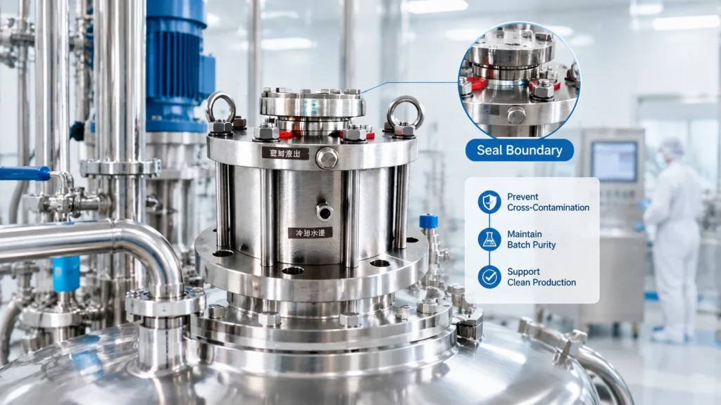
In a pharmaceutical reactor, choosing a seal support system is not simply a question of whether “dry” or “wet” is better. The practical question is which credible route could carry material across the seal boundary and into a batch, and how that route can be detected, controlled, and validated. A nitrogen barrier can avoid a liquid barrier-fluid inventory at the process boundary, while a liquid barrier system can provide lubrication and heat removal. Neither choice, by itself, proves product purity. The decision must account for seal-face wear, pressure relationships, cleaning and sterilization cycles, process chemistry, and the consequences of a single failure.
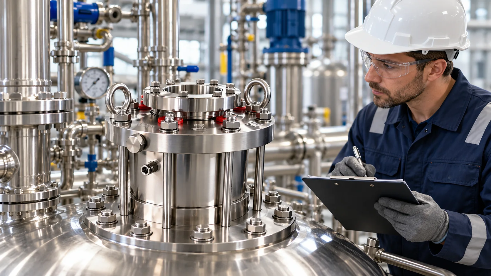
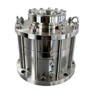
Xinyoumi lists reactor seals and auxiliary systems for pharmaceutical applications; confirm the exact arrangement against the reactor and project specification.
A useful contamination assessment traces a substance from its source to the product. For a reactor seal, consider at least four pathways: barrier or buffer medium crossing toward the process; process material escaping outward and later being introduced during maintenance; particles generated by rubbing faces or secondary components; and residues retained in crevices or low points that are mobilized during a later batch. The hazard depends on what the substance is, how much could transfer, when transfer might occur, and whether monitoring or downstream controls can detect it.
This is why a “clean” medium is not synonymous with a clean process. Nitrogen may be chemically compatible in a given application, but its pressure, purity, moisture, supply reliability, and failure response must be specified. A liquid may be selected for compatibility and lubrication, yet leakage, migration, degradation, or an incorrect fill can create a direct contamination concern. The process owner should define allowable ingress, product-contact boundaries, alert limits, and the action taken when a limit is exceeded.
In a dry-gas arrangement, nitrogen is supplied to a designated seal cavity or barrier interface. When the design and pressure balance are appropriate, this can reduce or remove a circulating liquid barrier inventory adjacent to the product side. That may simplify one potential contamination pathway: there is no barrier liquid to enter the batch through that route. It does not mean that the seal is particle-free, that the process is isolated under every fault, or that nitrogen is automatically acceptable for every formulation.
The key questions are configuration-specific. Is the gas barrier intended to leak toward the product, toward the atmosphere, or in another controlled direction? What pressure margin is required across the operating envelope, including startup, shutdown, upset, and loss of supply? Could gas flow affect foaming, oxidation control, solvent vapor behavior, or product quality? What happens if pressure falls, filters load, regulators fail, or the gas is interrupted? These scenarios belong in the equipment risk assessment and operating procedure, not in a generic claim that a dry arrangement prevents contamination.
A gas system also needs a defined quality specification and monitoring strategy. Confirm the nitrogen source and grade, point-of-use filtration where required, pressure and flow indication, alarm thresholds, and response to an out-of-range condition. Validate the supply arrangement against the actual seal design and process; do not infer operating pressure or allowable leakage from another service or a different model.
A liquid barrier or buffer system can support face lubrication, cooling, and a controlled operating environment. Depending on the arrangement, it may also establish a pressure differential intended to influence the direction of leakage. These functions can be valuable where the process, temperature, pressure, or seal design calls for them. They come with a separate batch-control task: identify the fluid, its inventory, its route, and the circumstances under which it could migrate toward the product.
Begin by checking fluid-product compatibility and the consequences of the smallest credible ingress, rather than asking only whether the fluid is “clean.” Consider toxicity, allergen status, extractables, impact on assay or downstream purification, and whether a transfer would be detectable. Define fill and replenishment controls, pressure and level alarms, inspection intervals, and what operators do after an unexplained level change. If the system uses a pressure differential, verify it across the complete pressure cycle and account for the possibility that the differential reverses during a transient.
A liquid system is not inherently unsuitable for pharmaceutical service; suitability depends on the fluid, design, process risk assessment, and validation. Even a compatible fluid may matter at low ingress levels in a sensitive product, so document the decision at the product-quality level.
Both gas-supported and liquid-supported seal designs rely on contacting or closely controlled sealing faces, depending on the specific design. Wear can generate particles from face materials, secondary seals, or adjacent components. The amount and type of debris depend on face pairing, surface finish, loading, alignment, shaft movement, speed, lubrication regime, temperature, process solids, and operating history. A gas barrier does not eliminate this mechanism, and a liquid barrier does not guarantee that debris stays out of the batch.
For contamination control, ask what materials are exposed to the process and what evidence is available for the proposed duty. Review the face and secondary-seal materials, the expected start-stop frequency, dry-running tolerance if relevant, and the effects of CIP/SIP temperature and pressure. Establish inspection criteria and a means to investigate wear after maintenance or an excursion. If particles are a critical quality attribute, include a justified monitoring or product-impact assessment; do not substitute a broad “low wear” statement for process-specific evidence.
Clean-in-place and sterilize-in-place cycles add conditions that may be more demanding than normal production. Cleaning solution chemistry, temperature, flow, pressure, drainability, and hold time can affect seal materials and leave residues in poorly swept areas. Steam-in-place adds thermal cycling and condensate behavior. A seal support arrangement must therefore be assessed as part of the assembled reactor boundary, not only as a component with a nominal temperature rating.
Map wetted surfaces and retention points around the shaft, chamber, connections, and drains. Confirm cycle exposure, drainability or sampling, and the system state before the next batch. Verify material compatibility and pressure/temperature limits from equipment documentation, then qualify cleaning and sterilization for the installed configuration and representative worst-case soils.
Do not assume a seal is CIP/SIP-ready because it is used on a pharmaceutical reactor or because one component withstands steam. The hygienic suitability of the whole assembly—including dead legs, surface condition, elastomers, connections, and maintenance practices—requires evidence. If the seal cannot be fully exposed to the validated cycle, the boundary and cleaning strategy need a documented alternative.
Before freezing the seal plan, review these points cross-functionally:

The outcome may favor a nitrogen dry-gas barrier where avoiding liquid ingress is a major objective and the gas system can be controlled reliably. It may favor a liquid barrier where lubrication, cooling, or the verified seal design requires it and ingress can be acceptably prevented, detected, or managed. Some services may need a different arrangement altogether. The choice should follow the risk assessment and equipment specification, not a universal dry-versus-wet rule.
For pharmaceutical reactors, contamination control depends on the pathway, not the label on the seal system. Nitrogen can remove one potential liquid-ingress route but still requires pressure, purity, and failure controls. A liquid barrier can support seal operation but requires explicit compatibility and migration safeguards. Both options require attention to face wear and particles, and both must be evaluated through CIP/SIP conditions and the validated cleaning strategy. Match the system to the product risk, verify the complete operating envelope, and document how excursions affect the batch.
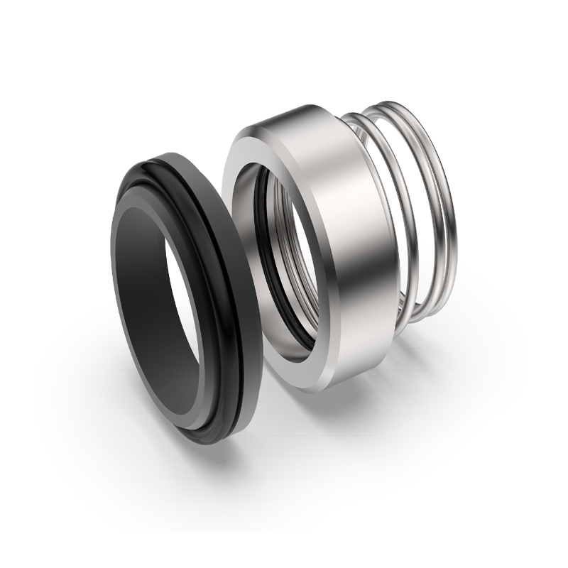
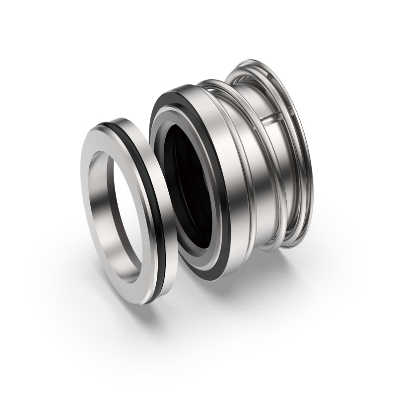
For a reactor-specific fit check, share the seal model or drawing, shaft dimensions, process fluid, pressure and temperature range, speed, cleaning/sterilization cycle, and the consequence of possible ingress. Xinyoumi reactor seal and auxiliary-system product range can help identify the relevant equipment family; use the Xinyoumi sealing solution overview for application context or contact the Xinyoumi team to discuss a project specification.
No. It can remove a liquid barrier medium from a particular boundary, but the actual leakage direction, process pressure, gas quality, seal configuration, and failure modes still need verification.
It may be a credible pathway depending on the arrangement and pressure conditions. Assess compatibility and migration scenarios, and define monitoring and response controls for the installed system.
No. Face and component wear remain design- and operating-condition dependent. Evaluate material pairing, loads, alignment, cycling, and maintenance for either support approach.
Review wetted surfaces, retained volumes, drainability, material compatibility, cycle temperature and pressure, condensate behavior, and evidence that the complete installed configuration can be cleaned and sterilized as intended.