Nullam dignissim, ante scelerisque the is euismod fermentum odio sem semper the is erat, a feugiat leo urna eget eros. Duis Aenean a imperdiet risus.
Nullam dignissim, ante scelerisque the is euismod fermentum odio sem semper the is erat, a feugiat leo urna eget eros. Duis Aenean a imperdiet risus.
 author
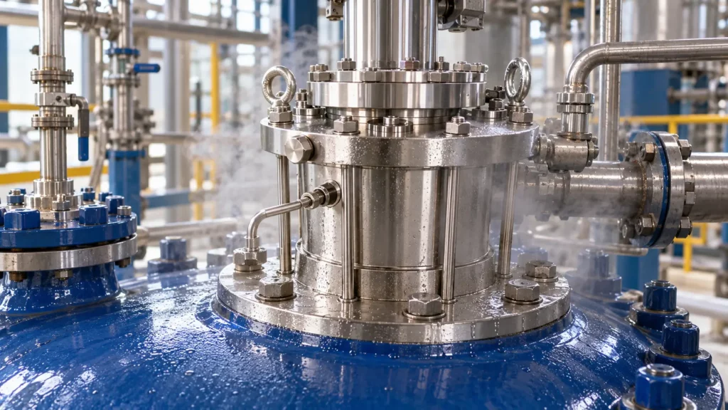
A seal elastomer can appear compatible with the reactor liquid and still deteriorate because the seal chamber is exposed to a different vapor mixture. In a glass-lined reactor, the dependable starting point is not a generic chemical-resistance chart: it is identifying what reaches each secondary seal during charging, heating, reaction, venting, cleaning, and shutdown. PTFE-based components, encapsulated seals, metal bellows, or an elastomer-free arrangement may be candidates, but each needs review against the actual phase, temperature, pressure, movement, and hardware geometry.
The key distinction is simple: the bulk liquid is not necessarily the seal’s full chemical environment. Volatile components can concentrate in a headspace or condense in a cooler seal region. A supplier therefore needs the liquid recipe and a credible description of the vapor that can contact the seal—not just the main solvent name.
A compatibility table typically describes a material exposed to one chemical under stated conditions. A reactor may present a changing mixture. During warm-up, the more volatile constituents can enrich the headspace; a pressure change can alter what condenses; and a seal housing can be colder than the vessel. Vapors may therefore contact an O-ring at a different composition and temperature than the liquid sample used for a compatibility check.
The relevant question is not whether a chemical is “compatible” in isolation, but whether the specific elastomer compound retains its sealing function across the exposure history. Swelling, shrinkage, softening, hardening, loss of resilience, permeation, or compression-set changes can affect static or dynamic sealing. A brief exposure and a long hot soak are not equivalent. Nor does a successful liquid immersion test automatically qualify a vapor-exposed component.
In glass-lined equipment, the sealing system also has to match the reactor’s shaft and mounting arrangement. A material substitution cannot correct a mismatch in dimensions, face loading, thermal management, or installation. Treat phase compatibility and mechanical fit as connected but separate review items.
Build an exposure map for each seal location. Identify which secondary seals see process vapor, which see liquid, and which are shielded or exposed to a buffer, flush, barrier, or cooling arrangement. Confirm whether the vapor can reach the location continuously, only during a batch step, or after shutdown. Ask whether condensate can form and remain trapped.
Record the normal and credible worst-case temperature and pressure at the seal, not only the vessel design limits. Include startup, upset, cleaning, sterilization if applicable, vacuum, depressurization, and cooling. Note shaft speed or oscillation, axial movement, and how often the equipment cycles. This context helps distinguish chemical attack from installation damage, thermal aging, extrusion, or mechanical wear.
Where composition changes during reaction, provide the operating sequence and explain what can be present at each stage. If the vapor composition is unknown, say so; a supplier may need process engineering input or a representative analysis before recommending a material.
No material family is a universal answer. The shortlist should be treated as a design discussion, followed by confirmation for the exact compound, geometry, and conditions.
PTFE is often considered where elastomer chemistry is the concern. However, “PTFE” does not by itself define a complete seal solution. A filled or modified PTFE part has a particular formulation and mechanical behavior; it may not provide the same elastic recovery as a conventional O-ring. Designers must consider creep, cold flow, sealing stress, surface finish, extrusion gaps, cycling, and the required movement. Confirm the exact grade and whether the component is a gasket, envelope, wedge, or another geometry.
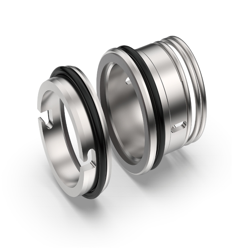
An encapsulated seal generally places a protective polymer jacket around an elastomeric core. It may reduce direct contact between the core and process media, but the jacket’s chemical and temperature limits, permeability, seam or joint construction, compression, and damage risk still matter. The core can remain vulnerable if vapor enters through a defect or exposed section. Verify whether the design is suitable for the gland dimensions and motion; do not assume encapsulation eliminates compatibility review.
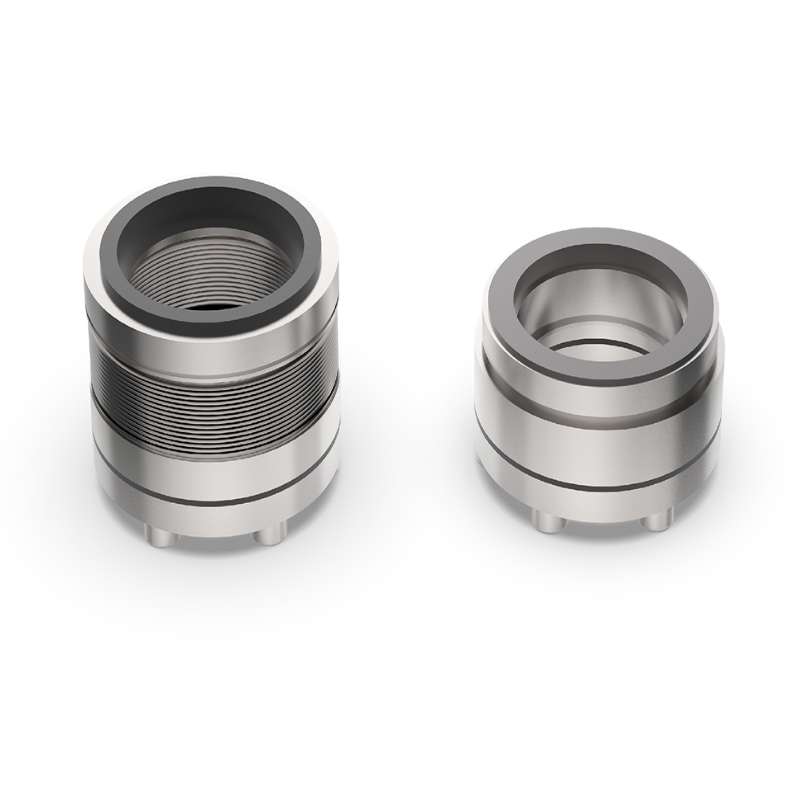
A metal-bellows seal can remove a sliding elastomer from a particular secondary-sealing function, depending on the seal architecture. It does not automatically make the complete assembly elastomer-free: static gaskets, auxiliary seals, or other interfaces may remain. The bellows alloy itself must be reviewed against the process environment, including condensation and contaminants. Bellows fatigue, pressure direction, temperature cycling, shaft movement, and the compatibility of all remaining wetted materials need engineering confirmation.
Where an elastomer cannot be qualified for the exposure, a design that minimizes or removes elastomer contact may be worth evaluating. “Elastomer-free” must be defined at component level: list every O-ring, gasket, backup ring, and auxiliary interface in the proposed assembly. A design change can alter installation, maintainability, dimensions, and load paths. For a glass-lined reactor, also verify that the proposed arrangement is intended for the vessel and its drive/mounting geometry rather than extrapolating from a pump seal.
A useful fit review begins with process detail, not a request for a material name. Send the information below, and identify what is measured, estimated, or still unknown.

Concentrations should be expressed as actual values or defensible operating ranges, not “dilute,” “trace,” or “mostly solvent.” If the vapor profile is not directly measured, share the best process-based estimate and label it clearly. The supplier can then identify the assumptions that need confirmation and whether a material test, process review, or design change is appropriate.
First, locate the failed secondary seal and determine which phase reached it. A damaged O-ring alone cannot establish vapor attack; inspect for swelling, cracking, flattening, extrusion, abrasion, heat damage, and assembly marks, and compare findings with the process timeline. Then build a component-by-component exposure list and screen candidate compounds against the full mixture and exposure conditions.
Next, confirm mechanical suitability. Review gland dimensions, squeeze, clearance, surface finish, motion, pressure direction, temperature range, and any cooling or auxiliary system. Check the complete bill of materials so a proposed PTFE or bellows solution does not leave an unreviewed elastomer elsewhere. If compatibility remains uncertain, agree with the supplier on a representative qualification approach and acceptance criteria before changing the installed design.
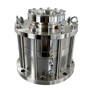
For reactor applications, XYM lists dedicated reactor-seal models and identifies certain models as suitable for glass-lined reactors. That establishes product relevance, not universal chemical compatibility. The specific model, materials, conditions, and interfaces still need to be checked against the application. Begin with the reactor seal product range, and, where useful, review the 2009U/2010U reactor seal information. The broader reactor seal selection guide can help organize operating data, while this vapor-focused review adds the missing phase-by-phase exposure detail.
When a liquid-compatible O-ring fails in a glass-lined reactor, investigate the phase that actually reached it. Vapor enrichment, condensation, transient temperatures, and the complete batch cycle can change the exposure materially. PTFE-based parts, encapsulated seals, metal bellows, and reduced- or no-elastomer designs each address different constraints; none should be selected by material label alone. A reliable recommendation depends on a component-level materials list, liquid concentrations, vapor composition, local conditions, and mechanical fit.
Yes. The vapor mixture, temperature, duration, and possibility of condensation may differ from the liquid test conditions. Compatibility should be evaluated for the actual exposure at the seal location.
No. PTFE-based designs have different recovery and mechanical behavior from elastomer O-rings. Exact formulation, geometry, gland design, motion, load, and exposure all require review.
Not necessarily. A bellows may replace one dynamic secondary-seal function, while static or auxiliary elastomer seals remain elsewhere. Ask for a complete component-level materials list.
Provide known or estimated species and fractions or partial pressures, how the estimate was obtained, condensable components, expected reaction products, and the temperature-pressure-time sequence at the seal.
For a fit check, share the reactor model or seal drawing, full liquid composition and concentration ranges, vapor profile, local operating cycle, and failure evidence with the XYM technical team.