Nullam dignissim, ante scelerisque the is euismod fermentum odio sem semper the is erat, a feugiat leo urna eget eros. Duis Aenean a imperdiet risus.
Nullam dignissim, ante scelerisque the is euismod fermentum odio sem semper the is erat, a feugiat leo urna eget eros. Duis Aenean a imperdiet risus.
 author
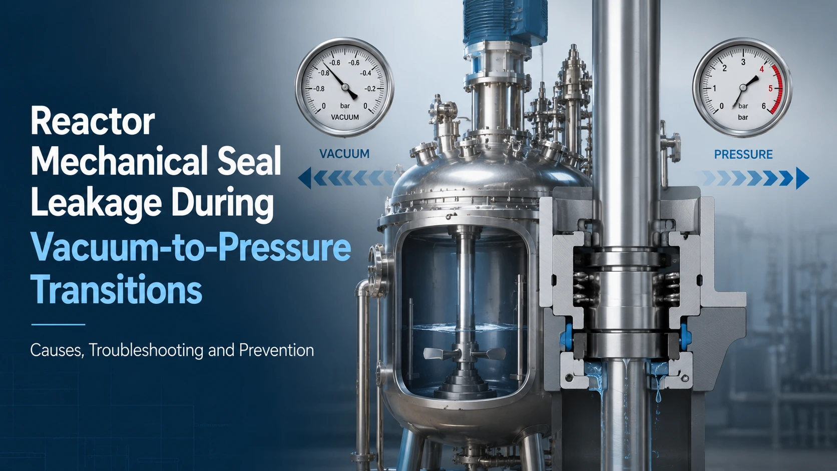
Reactor mechanical seal leakage during a vacuum-to-pressure transition is rarely solved by installing the same seal again. It may begin during evacuation, atmospheric recovery, positive-pressure buildup, or agitator startup. Each pattern points to different seal-face loading, support pressure, shaft movement, installation condition, or process behavior. Troubleshooting should begin with the pressure-cycle timeline.
The available Xinyoumi mechanical seal solutions include reactor seals and sealing auxiliary systems, but the correct configuration depends on the reactor, medium, temperature, pressure sequence, shaft data, and operating method.
A seal may remain stable at constant vacuum or positive pressure yet leak while moving between them. Maximum pressure describes only part of the duty. Differential direction, rate of change, thermal movement, agitator startup, and support-system response can change the load on the sealing faces.
During vacuum operation, atmospheric or support pressure may act toward the process side. As the vessel returns to atmospheric pressure and builds positive pressure, the differential can reduce, reverse, and rise again. A seal that works in one direction may become unstable in the other.
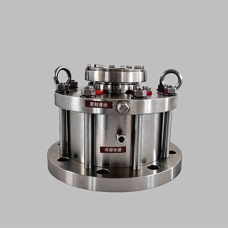
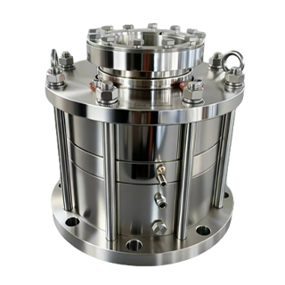
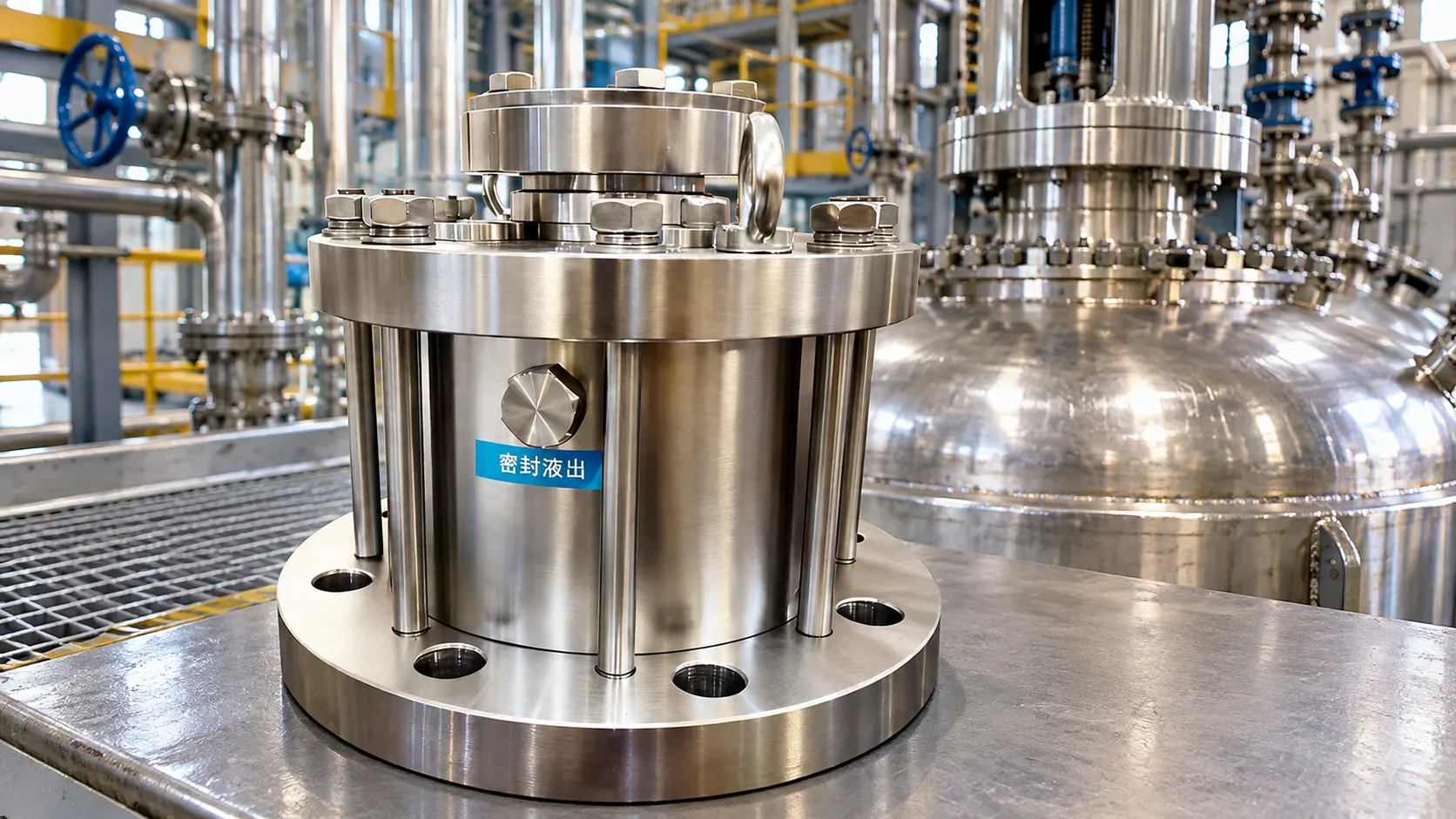
Confirm whether the seal is intended for negative and positive pressure. Xinyoumi’s 2020B/2020W platform is published for glass-lined, steel, and special-material reactors, with a modular, bidirectionally balanced structure and a design-pressure range of -0.1 to 1.6 MPa. The bidirectionally balanced reactor seal design is relevant to this duty, but the published range does not confirm ramp rate, cycle count, transient spikes, or service life for a particular process.
In a dual seal, fluid between the seals may act as a buffer or pressurized barrier. A buffer is below process pressure and collects leakage; a barrier is above process pressure and limits process-fluid movement toward the atmosphere.
Leakage may occur when process pressure changes faster than the support system responds. Causes include pressure loss, restricted valves, low fluid level, trapped gas, high temperature, or incorrect instrumentation. Raising barrier pressure without diagnosis can alter face loading or increase barrier-fluid entry into the reactor. Compare process and support-system trends on the same timeline.
Record the first visible leak, pressure decay, fluid loss, or alarm before dismantling the seal. Timing often narrows the cause better than the final condition after shutdown.
A leak while pulling vacuum may involve a static joint, damaged secondary seal, unstable face contact, or a support system that was not ready before evacuation. If the vessel cannot hold vacuum while stationary, inspect gland connections, O-rings, V-rings, and instrument fittings first.
If vacuum is stable while stationary but deteriorates after the agitator starts, shaft runout, axial movement, vibration, or dynamic face behavior becomes more likely. Record minimum absolute pressure, evacuation time, agitator status, support pressure, and whether leakage stops when rotation stops.
Leakage as vacuum is released may indicate pressure reversal, delayed barrier response, or restricted secondary-seal movement. Leakage during positive-pressure buildup may point to insufficient barrier differential, face damage, or an unsuitable arrangement. Shutdown leakage can be associated with cooling, crystallization, deposits, or thermal movement.
| Leakage timing | Data to record | Likely cause | First inspection |
|---|---|---|---|
| Vacuum pull-down | Pressure, evacuation rate, support status | Static leak or imbalance | Gaskets and fittings |
| Vacuum hold | Pressure decay and shaft status | Static joint or face instability | Hold test |
| Return to atmosphere | Pressure when leakage starts | Reversal or delayed response | Pressure history |
| Positive-pressure buildup | Process and barrier pressure | Low differential or damage | Support system and faces |
| Shutdown | Pressure and temperature decay | Deposits or thermal movement | Faces and secondary seals |
A new seal will not correct an uncontrolled support system, excessive shaft movement, installation damage, or material incompatibility. Preserve failed parts and operating records before choosing a replacement.
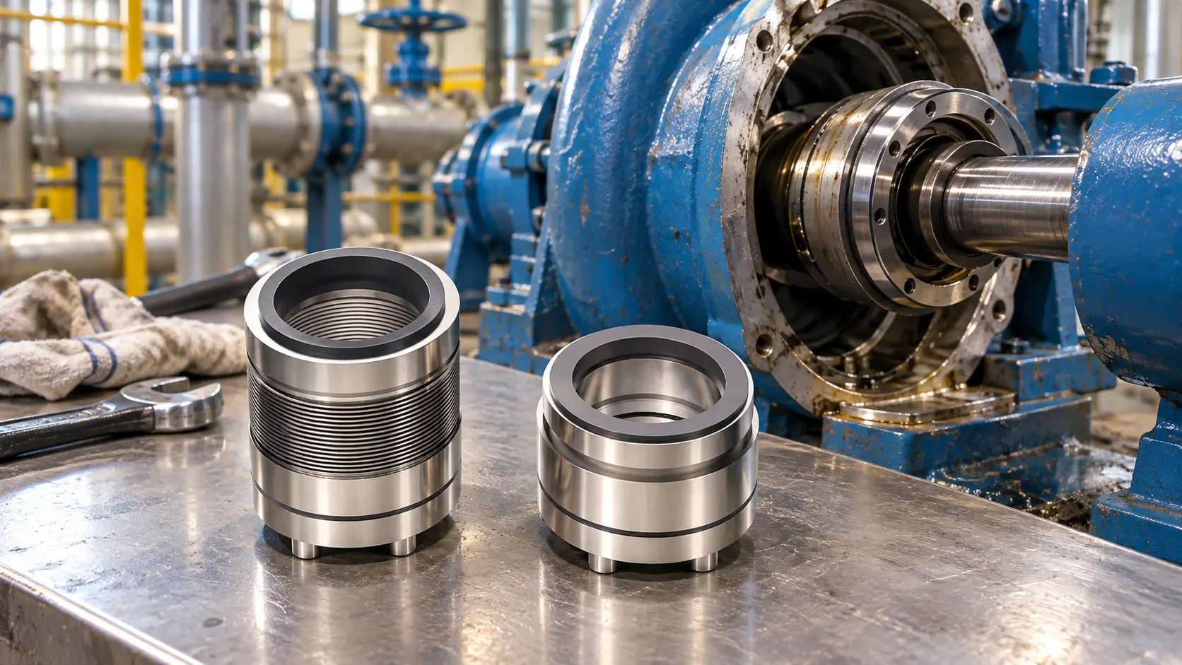
Check faces for scratches, chipping, uneven tracks, thermal discoloration, dry-running marks, and adhered product. Inspect secondary seals for swelling, hardening, cuts, extrusion, or restricted movement. Deposits may indicate crystallization, polymerization, solids accumulation, or loss of lubrication.
Minor damage may be repairable after dimensional checks. Severe scoring, distorted parts, or chemically damaged secondary seals generally require replacement. Review materials against the actual medium, concentration, cleaning chemicals, temperature, and solids content rather than copying the old seal.
Repeated agitator mechanical seal leakage after replacement often indicates a condition outside the seal. Measure shaft runout and axial movement, inspect bearing and gearbox condition, verify gland alignment, and check the shaft sleeve. Uneven tightening, incorrect compression, damaged faces, and contamination can also cause early leakage.
A visually identical seal may fail if it cannot accommodate actual movement or geometry. Xinyoumi’s technical materials identify equipment type, shaft size, medium, temperature, pressure, speed, and installation method as core inputs; drawings, photographs, samples, or field dimensions can support replacement analysis.
For a dual seal, inspect the complete support loop. Check pressure stability, fluid level, circulation, temperature, cooling, valves, restrictions, and alarms. Unexpected fluid consumption may indicate leakage into the process, leakage to the atmosphere, or a support-system fault.
The fluid must remain compatible with the process and seal materials. Contamination, vaporization, degradation, or excessive viscosity can reduce lubrication and heat removal. Restart only after the system has been filled, vented, pressurized, and checked.
Confirm that the support system is active before evacuation, agitation, heating, or pressurization. Review valve operation and pressure-change timing. Trend process pressure, support pressure, temperature, fluid level, and leakage through a controlled cycle after maintenance.
Higher pressure is not a substitute for diagnosis. If pressure tracking is inadequate, the support system, instrumentation, or sequence may need modification. Deposits formed during cooling may also require changes to cleaning or purge steps. New setpoints should be approved for the specific arrangement and process.
Repair may suit a proven configuration when damage is limited to serviceable faces, secondary seals, springs, or other replaceable parts. Direct replacement is appropriate when the arrangement is verified for the full pressure cycle and failure resulted from wear or installation damage.
Consider redesign when failures repeat, the seal was not verified for both pressure directions, the support system cannot maintain the required condition, or shaft movement exceeds existing capability. Compare available reactor mechanical seal systems rather than ordering only by the old model. The range includes designs for vertical steel, glass-lined, and special-material reactors.
A useful quotation requires operating data and dimensions:
Missing data should be listed as assumptions or items requiring confirmation.
A suitable supplier should review the complete duty rather than match only the shaft diameter or old model. The response should explain the arrangement, pressure direction, material basis, support-system requirements, dimensions, serviceable parts, and unresolved risks.
Kunshan Xinyoumi Mechanical Seal Technology Co., LTD publishes reactor mechanical seals, pump seals, and sealing auxiliary systems for petrochemical, pharmaceutical, food, and new-energy applications. Its stated approach includes modular design and selection based on equipment and operating conditions.
The quotation should state whether replacement requires changes to the shaft, flange, drive, or installation height. Warning signs include recommendations made without process data, absolute no-leakage promises, or claims that a static rating proves suitability for repeated transitions.
Reactor mechanical seal leakage during a vacuum-to-pressure transition should be diagnosed by the stage at which it begins. Compare process and support-system trends, inspect faces and secondary seals, measure shaft movement, and review the operating sequence before purchasing another seal.
For a replacement or retrofit review, submit the pressure cycle, medium, temperature, speed, shaft and flange dimensions, current drawing, support-system details, required quantity, and failure photographs. Buyers can request a reactor seal assessment to confirm which information is sufficient for a technical proposal.
It may, but suitability depends on seal balance, pressure direction, support system, size, speed, temperature, and the actual cycle. Verify the application against the product specification rather than relying only on maximum pressure.
The support system may not be stable before evacuation or rotation, pressure may reverse, or shaft movement may begin when the agitator starts. Compare leakage timing with process pressure, support pressure, temperature, and shaft status.
Not necessarily. Low pressure can be a problem, but excessive pressure can change face loading or increase barrier-fluid entry into the process. The correct differential depends on the arrangement and application.
Provide minimum vacuum, maximum pressure, transition sequence, temperatures, medium details, shaft and flange dimensions, speed, shaft movement, existing seal information, support-system data, quantity, and failure photographs.