Nullam dignissim, ante scelerisque the is euismod fermentum odio sem semper the is erat, a feugiat leo urna eget eros. Duis Aenean a imperdiet risus.
Nullam dignissim, ante scelerisque the is euismod fermentum odio sem semper the is erat, a feugiat leo urna eget eros. Duis Aenean a imperdiet risus.
 author

Selecting a mechanical seal for a slurry pump is a process decision, not a catalog lookup. Ore, tailings, sand, crystals, and sludge can abrade faces and destabilize lubrication. Start with the slurry profile, then check pressure, speed, temperature, shaft geometry, and operating pattern. This guide shows where a heavy-duty slurry seal such as G50(F)S slurry pump seal may fit. Confirm limits against the final drawing and application data.
A slurry pump seal sees a moving mixture rather than a clean liquid film. Hard particles can score the mating faces; fibrous solids can bridge a gap; crystals can build deposits around springs or sleeves. Higher solids also increase torque and heat generation. A seal that performs acceptably on clear water may fail quickly when the same pump handles a concentrated mineral stream.
The objective is to keep particles away from closing faces and preserve alignment through starts and stops. Seal type, materials, flushing, and installation must be evaluated as one system.
Record operating data from the process, not only the pump nameplate. Ask the process and maintenance teams for the following values:
Do not substitute a generic ‘abrasive’ label for measurable data. Particle size and chemistry can change the wear mechanism even at the same solids percentage.
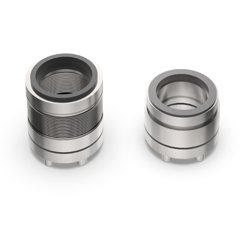
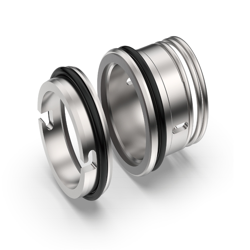
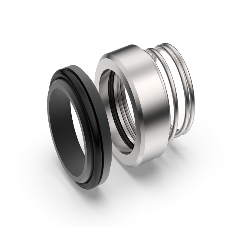
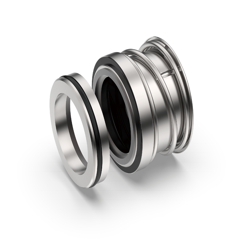
For highly abrasive, high-solids service, a purpose-designed slurry mechanical seal is generally more defensible than adapting a light-duty water-pump seal. The architecture should limit particle ingress, tolerate higher face loading, and provide a predictable path for heat removal or flushing when the application requires it.
A single seal may suit compatible, lower-risk service. A dual seal may be justified when leakage control, hazardous liquid, or lubrication reliability requires a barrier or buffer system. The choice depends on pump design and environmental requirements, not pressure alone.
Cartridge construction can reduce setting errors during replacement, while a component arrangement may be preferred where dimensions or retrofit constraints demand it. Whichever format is chosen, verify the shaft, sleeve, gland, and chamber dimensions before release to production. Xinyoumi’s pump seal product range includes multiple pump-seal configurations, so the final model should be matched to the actual pump rather than selected from the family name alone.
Seal faces must balance abrasion resistance with lubrication behavior. Silicon carbide is often considered for severe wear, while tungsten carbide or carbon-based faces may suit other combinations. Pairing depends on solids, chemistry, speed, and cooling; a harder face is not automatically better if the opposing face or thermal path is unsuitable.
Secondary seals must tolerate the liquid and the full temperature range. FKM, EPDM, PTFE, and perfluoroelastomer options each have different chemical and thermal limits. Check compatibility with the actual process fluid, cleaning chemicals, and any barrier or flush fluid. Springs, metal components, and gland materials also need corrosion review, especially in chloride-bearing or acidic slurries.
Request the supplier’s material pair, elastomer designation, and operating envelope in writing. If a material is listed as an option, treat it as conditional until the supplier confirms it for your exact concentration, temperature, pressure, and speed.
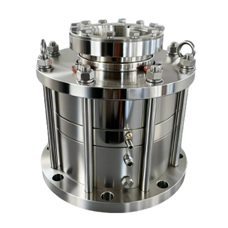
The G50(F)S page identifies the series as integrated mechanical seals for slurry pumps and places it in the heavy-duty slurry category for highly abrasive, high-solids media. Its published envelope is -20 to 220 degrees C, reduced to -20 to 120 degrees C for chemical slurry conditions; maximum shaft surface speed is 23 m/s; maximum pressure is 2.5 MPa, with 1.6 MPa listed for standard working conditions; and the standard shaft diameter is 85 mm or larger, with non-standard customization supported.
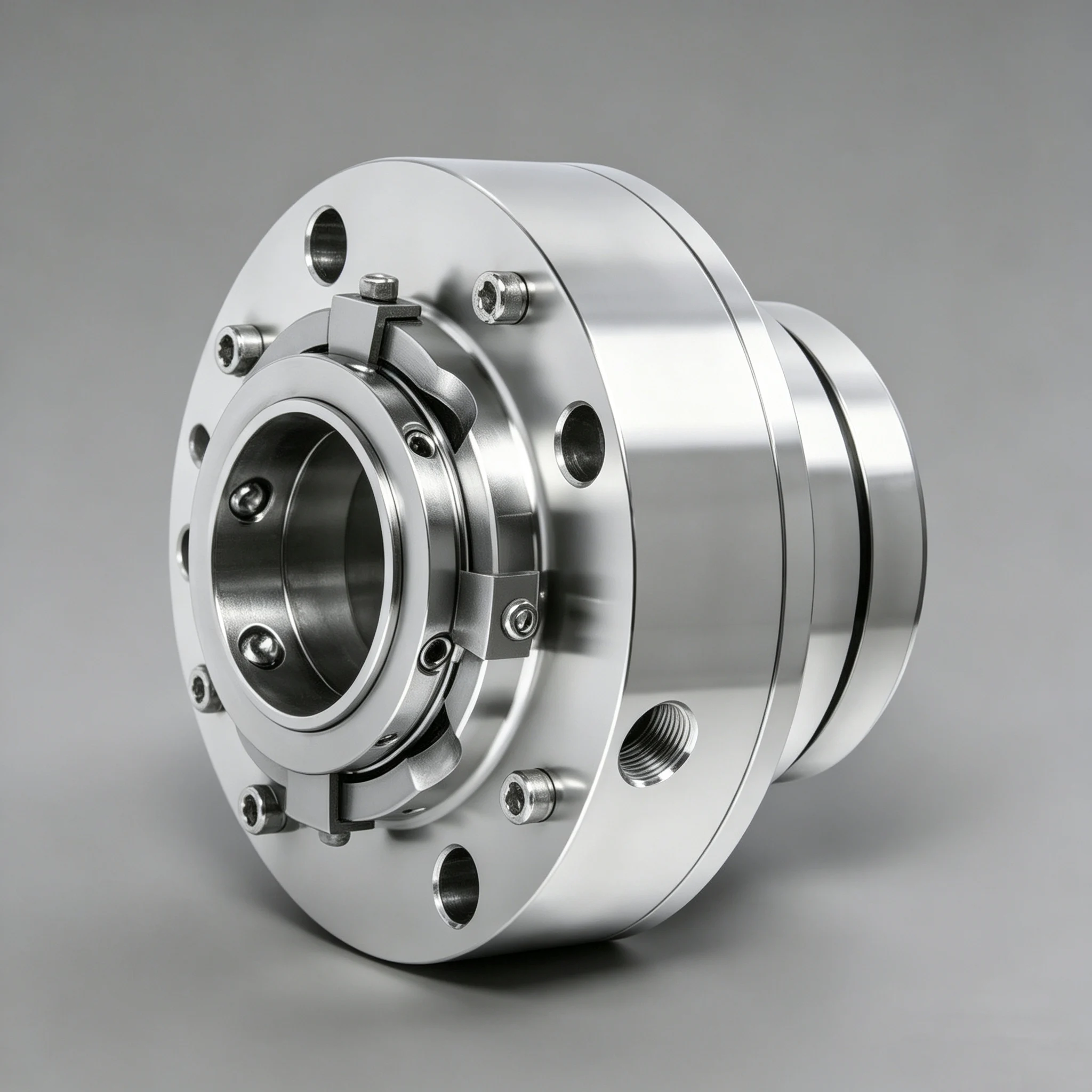
The same page describes tailings, coal washing, and metallurgical treatment, including media with solids up to 60% and particles up to 6 mm. It also lists phosphorus, salt, and titanium-dioxide production, where anti-crystallization and anti-clogging behavior matters, plus municipal sludge and grit-chamber service with fibers and sand. These are screening signals, not permission to exceed published limits; confirm particle size, chemistry, pressure, speed, and shaft dimensions before specifying.
Many premature failures blamed on material selection are actually caused by operation. Keep the pump within its stable flow range, avoid running dry, and prevent air from entering the seal chamber. If a flush or cooling circuit is specified, verify flow, pressure, cleanliness, and instrument alarms. Dirty flush water can introduce more damaging particles than the process itself.
Inspect vibration, bearing condition, shaft runout, and coupling alignment as part of seal troubleshooting. A new seal cannot compensate for a bent shaft, loose bearing, distorted gland, or excessive axial movement. Record leakage, temperature, pressure, and flush conditions at startup so the maintenance team has a baseline for trend analysis.
Before ordering, send the pump model, seal chamber drawing, shaft and sleeve dimensions, rotation, operating envelope, slurry composition, and any photos of the failed seal. Include the reason for replacement: face scoring, elastomer swelling, spring clogging, overheating, leakage at startup, or short running life. A clear failure description helps the supplier distinguish a design issue from an installation or operating issue.
During installation, protect lapped faces from grit, use the specified lubricant, confirm setting dimensions, and check that the gland is square to the shaft. Clean the chamber and flush lines before assembly. For repeat purchases, Xinyoumi’s pump seal replacement RFQ checklist can help organize the dimensions, drawings, failure evidence, and purchasing requirements needed for a traceable quote.
A credible quotation should show seal faces, elastomers, metal materials, pressure and speed basis, and any auxiliary system. Ask how non-standard shafts are handled, what inspection records accompany the seal, and which limits require written approval. Compare operating fit, not unit price alone.
For complex slurry duties, a supplier should be willing to review the pump drawing and process conditions before recommending a model. Xinyoumi describes a one-stop service system covering selection through operation support. Treat that as a reason to request an application review, not as a substitute for checking the final technical specification.
A reliable slurry pump mechanical seal starts with a complete media profile and ends with verified installation and operating controls. Define solids, particle size, chemistry, pressure, temperature, speed, and shaft movement; choose architecture and materials together; then confirm flushing, alignment, and replacement data. For a heavy-duty candidate such as G50(F)S, the published application envelope provides a useful screening point, while the final selection must still be checked against the specific pump and slurry.
To request a fit check, contact the technical team with the pump model, seal dimensions, slurry composition, solids and particle size, pressure, temperature, speed, shaft movement, drawings, photos, and required quantity.
It may work only in mild, well-controlled service. High solids, sharp particles, crystals, or poor flush quality usually require a dedicated slurry design and a documented material review.
There is no single value. Solids concentration, particle size and hardness, chemistry, pressure, temperature, speed, and shaft movement must be evaluated together.
Consider it when leakage control, hazardous media, or lubrication reliability justifies an engineered barrier or buffer system. Confirm the auxiliary system and monitoring requirements with the supplier.
The shaft diameter is a key dimension, but chamber geometry, setting length, speed, pressure, and gland arrangement also determine fit. Use the equipment drawing for final verification.