Nullam dignissim, ante scelerisque the is euismod fermentum odio sem semper the is erat, a feugiat leo urna eget eros. Duis Aenean a imperdiet risus.
Nullam dignissim, ante scelerisque the is euismod fermentum odio sem semper the is erat, a feugiat leo urna eget eros. Duis Aenean a imperdiet risus.
 author
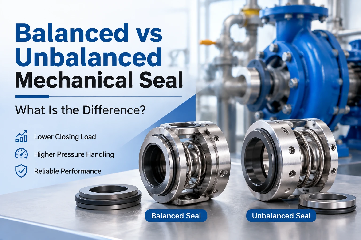
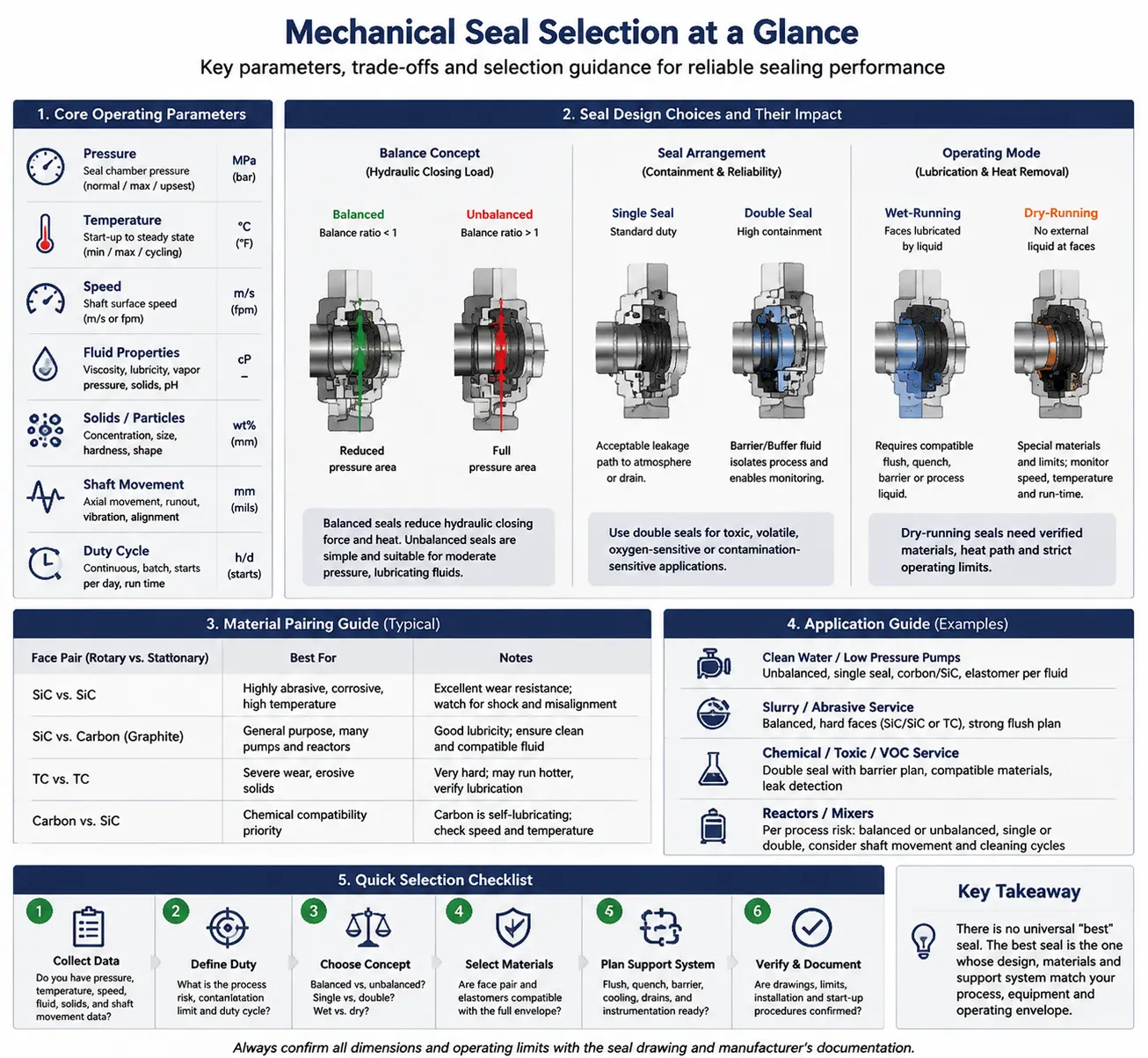
The practical difference between a balanced and an unbalanced mechanical seal is how much process pressure acts on the closing faces. A balanced design reduces hydraulic closing load, so it is generally considered for higher pressure, speed, poorer-lubricity or heat-sensitive services. An unbalanced design leaves a larger pressure area exposed; it is simpler and can be economical for clean, lubricating fluids at moderate pressure. The right choice still depends on geometry, materials, speed, temperature, pressure, fluid properties and equipment arrangement.
A mechanical seal closes the gap between a rotating shaft and a stationary housing with two very flat faces. A spring or bellows supplies initial closing force, while process pressure adds hydraulic force. The balance ratio expresses the effective hydraulic area divided by the face area. In common engineering notation, a ratio below 1 is called balanced and a ratio above 1 is called unbalanced. The ratio is a design parameter, not a quality score: it tells the engineer how strongly pressure loads the faces.
When the pressure area is reduced, the faces can maintain a controlled lubricating film with less friction. That can reduce heat and wear, but the design may be more sensitive to shaft movement, cavitation, vibration or installation errors. A higher pressure load can make an unbalanced arrangement stable in some services, yet it increases face loading as pressure rises. Verify the balance ratio and allowable envelope against the manufacturer’s drawing or datasheet.
| Criterion | Balanced design | Unbalanced design |
| Pressure loading | Lower effective closing load; better suited when pressure makes face heat or wear a concern. | Higher effective closing load; practical when pressure is moderate and the fluid provides lubrication. |
| Typical use logic | Consider for higher pressure, speed, temperature or low-lubricity duties after checking the full specification. | Consider for clean, lubricating services where simplicity and cost are important. |
| Operating sensitivity | Can require tighter control of alignment, movement, cooling and face materials. | Often more tolerant of some movement, but pressure increases face loading and wear risk. |
| Selection risk | Too little load or poor support can cause instability, leakage or face opening. | Excessive load can increase friction, heat, power loss and premature face wear. |
In a balanced seal, a shoulder, step or other geometry moves the pressure boundary closer to the center of the face. The fluid still presses on the assembly, but the projected area creating closing force is smaller. Balanced designs are therefore considered when pressure, speed or low lubricity could produce excessive face temperature. The effect is hydraulic; it is separate from whether the seal is single or dual, pusher or non-pusher, cartridge or component.
Balance does not remove the need for a stable fluid film. Dry running, blocked flush lines, solids, flashing or poor face cooling can damage either design. Face materials, secondary seals and the support system must be selected together. For corrosive, toxic or product-sensitive duties, a dual seal or a dry-running arrangement may be more relevant than balance alone.
An unbalanced seal can be a sound choice for a pump handling a clean, lubricating liquid at moderate pressure and temperature, especially when the equipment has a conventional shaft and a well-controlled operating point. Its geometry is typically straightforward, and the lower design complexity can simplify maintenance or replacement. These are selection tendencies, not universal limits; the allowable pressure must come from the seal specification.
Avoid choosing by pressure in isolation. A low-viscosity liquid, poor lubrication, frequent starts, abrasive particles or high surface speed can create heat even when nominal pressure is modest. Check the pressure at the seal chamber, not only the discharge pressure, and account for temperature rise, vapor pressure and transient conditions such as startup, shutdown and dead-heading.
Use the following sequence before requesting a replacement or new design:
Leakage immediately after startup often points to incorrect setting length, damaged faces, contamination or a missing gasket rather than the balance category itself. Leakage that increases with pressure may indicate excessive face loading, a pressure limit being exceeded or inadequate cooling. Rapid wear with a lubricating liquid can indicate misalignment, vibration, solids or an unsuitable face combination. Face opening during operation can result from cavitation, shaft deflection, thermal distortion or insufficient closing force.
Troubleshooting should begin with operating data and inspection evidence. Record when the leak starts, where the product appears, whether the seal faces are glazed or scored, and whether the support system is flowing. Do not change from unbalanced to balanced solely because a seal leaked; identify the load, heat and fluid-film cause first.
A useful RFQ gives the supplier enough information to check balance, materials and support systems together. Include the equipment model, shaft diameter, seal chamber drawing, normal and maximum pressure, temperature, speed, fluid and concentration, solids or crystallization risk, and the required leakage or emissions standard. State whether the seal is for a pump, reactor or another rotating machine and whether the installation is a replacement or a new design.
For a broader equipment and configuration review, see Xinyoumi’s mechanical seal products. The company publicly lists pump seals, reactor seals and auxiliary equipment; final suitability remains specification-dependent.
Where the duty involves unusual pressure, temperature, toxicity or contamination control, one-stop technical service can help organize selection, configuration and project support around the operating conditions.
Kunshan Xinyoumi Mechanical Seal Technology Co., LTD states that it designs, develops, manufactures and sells fluid mechanical seals, including pump mechanical seals, reactor mechanical seals and sealing auxiliary systems. Its public application pages cover chemical processing, pharmaceutical and food equipment, and new-energy lithium-battery production. Those application categories are relevant when the seal decision includes pressure control, hazardous media, cleanliness or thermal movement, but the exact balance design and materials should be verified for each duty.
For process-specific context, review the chemical-industry sealing solution and compare its stated application scope with your equipment data.
For a fit check or RFQ, contact the technical team with the model, dimensions, materials, load, operating conditions, drawing and quantity.
Balanced and unbalanced mechanical seals use the same basic face-sealing principle, but they distribute process pressure differently. A balanced seal reduces hydraulic closing load and is often considered for demanding pressure, speed, temperature or lubrication conditions. An unbalanced seal can be economical and effective in moderate, clean, lubricating service. The defensible selection is the one that matches the balance ratio, materials, support system, equipment geometry and real operating transients. Treat the category as a starting point for engineering review, not as a substitute for a verified specification.
No. It may reduce hydraulic face loading, but the complete seal and support system still determine reliability. An unbalanced seal can be appropriate for a moderate, lubricating service when its specified limits are respected.
It generally identifies a balanced design: the effective hydraulic area creating closing force is smaller than the reference face area. The exact ratio and allowable conditions depend on the seal geometry.
Only after checking dimensions, setting length, face materials, secondary seals, chamber pressure and the support system. A different balance design can change heat generation and operating behavior.
No. Balance is a hydraulic loading classification. Single or double describes the number and arrangement of seal faces; the classifications can be combined.