Nullam dignissim, ante scelerisque the is euismod fermentum odio sem semper the is erat, a feugiat leo urna eget eros. Duis Aenean a imperdiet risus.
Nullam dignissim, ante scelerisque the is euismod fermentum odio sem semper the is erat, a feugiat leo urna eget eros. Duis Aenean a imperdiet risus.
 author

A reactor nozzle standard is a useful starting point for mechanical seal selection, but it is not proof that two seals are interchangeable. The standard or vessel designation helps identify the mounting interface and dimensional family. The final match still depends on the actual flange drawing, shaft diameter, installation height, rotation, runout, operating conditions, and seal construction. This distinction matters when comparing glass-lined and steel vessels: the vessel material alone does not determine which seal fits.
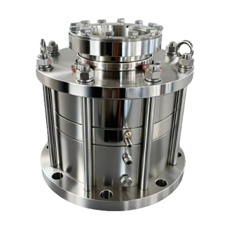
A vessel nozzle is the connection where the seal assembly mounts to the reactor. A referenced standard may define a family of nominal dimensions, such as flange arrangement, bolt pattern, and mounting geometry. It can make equipment identification faster and provide a common language between the vessel maker, maintenance team, and seal supplier.
It does not necessarily identify every feature needed to manufacture a replacement. Vessel age, manufacturer options, prior modifications, adapters, and nonstandard orders can leave an installed reactor different from a generic drawing. Even when two documents use the same designation, confirm the revision and the actual dimensions. Nominal size is not a substitute for a measured interface.
The supplied Xinyoumi reference material distinguishes steel-vessel and enamel-lined-vessel standard families and associates some legacy and current model families with different mounting standards. Because some codes and dates in the scan are difficult to read and may refer to older editions, treat them as clues for reviewing the vessel documents, not as a current compliance statement. Ask the vessel manufacturer or responsible engineer to confirm the governing drawing and revision.
A glass-lined reactor has a steel pressure boundary with a protective glass lining on process-contact surfaces. Its seal mounting interface is still defined by the vessel and nozzle design, but maintenance must also preserve clearances and avoid loading or contacting the lined area. The seal should be matched to the specified vessel connection and the actual assembly geometry; do not assume a steel-reactor model fits because the outside flange appears similar.
For a steel vessel, the nozzle and seal gland may follow a different dimensional family or project-specific drawing. The steel construction does not make the mounting dimensions universal. Confirm gasket seating, bolt engagement, gland depth, and any adapter or spacer in the installed stack. A retrofit that changes stack height can affect the seal’s working position, even if the bolt holes line up.
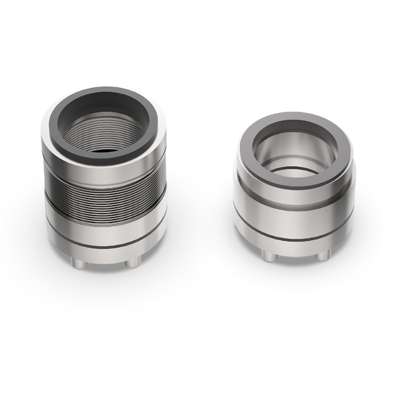
Xinyoumi’s reactor portfolio lists configurations for steel, glass-lined, and special-material vessels, including the 2021J and X212W/X212B families. These product listings establish that the company serves both vessel groups; they do not establish interchangeability between a particular reactor and a particular seal. Compatibility remains a drawing-and-measurement decision.
A reliable cross-check follows the load path from vessel to shaft. Start with the nozzle or vessel-head drawing, then compare the seal gland and any adapter against it. Record the following items from controlled drawings or field measurements:

Use the same datum and units across the vessel drawing, seal drawing, and field measurements. For example, an installation height measured from the vessel flange face cannot be compared directly with a dimension referenced from the seal carrier shoulder. Photographing a tape measure can help document the field condition, but it should supplement—not replace—a dimensioned drawing.
The vessel standard and the seal standard may come from different documents and serve different purposes. One may describe reactor equipment geometry; another may describe seal dimensions or technical requirements. A seal model’s standard code should therefore be read alongside the actual outline drawing and order specification. Do not infer that a code on a nameplate proves the installed seal conforms to a current edition or that another maker’s product has the same working dimensions.
When documentation is incomplete, send the supplier the vessel nameplate, nozzle and gland photographs, an overall side view, a shaft-end view, and measured dimensions with datum points marked. Ask the supplier to return a drawing showing the proposed mounting interface, installation height, shaft connection, and any adapter. Resolve discrepancies before ordering. If the vessel has been modified, identify who approved the modification and which dimensions now control.
For a legacy glass-lined vessel, note any restrictions on loads or contact near the lining and confirm them with the vessel documentation. Avoid using the seal flange to correct a damaged or misaligned vessel nozzle unless an engineered repair plan permits it. A seal can compensate only within its designed movement and alignment range; it cannot make an uncertain pressure-boundary connection acceptable.
Once the mechanical interface is established, select the seal arrangement for the process. Confirm pressure, vacuum, temperature, fluid properties, solids, cleaning regime, leakage-control objective, and utility availability. For glass-lined and steel equipment alike, process compatibility and contamination control remain separate checks from nozzle fit. A flange match does not establish suitability for the service.
Also review shaft runout and axial travel at the seal location. Excess runout can disturb face tracking; incorrect installation height can shift the seal away from its intended working position; and the wrong rotation or connection details can compromise operation. Give the supplier actual values and operating context rather than asking for a replacement based only on a model number.
Xinyoumi’s reactor mechanical seal range and X212W/X212B product information can help identify candidate configurations for discussion. Use the published information to shortlist a family, then confirm the exact interface and operating specification with a supplier drawing.
Reactor nozzle standards help organize seal selection, but they do not replace verification of the installed vessel. Glass-lined and steel reactors may use different interface families, and either may have legacy, adapted, or project-specific dimensions. Confirm the governing standard edition, compare the full flange and gland stack, measure the shaft and installation position, and check rotation and runout before choosing a seal. A documented fit check reduces the risk of ordering a seal that appears compatible by label but does not fit or operate correctly.
For a fit review, send Xinyoumi the vessel type and model, nozzle and gland drawings, shaft diameter, installation height, rotation, runout, process conditions, and photographs of the installed interface. The reactor seal product range is a starting point for identifying the relevant product family.
No. It may identify a dimensional family, but the installed flange, gland depth, shaft connection, working height, adapters, and design revision still need to be checked.
Only when the vessel connection, mounting stack, clearances, shaft interface, and service requirements are confirmed for that specific installation. Similar external flange dimensions alone are not enough.
Provide the nozzle and bolt-circle dimensions, flange facing, gland depth, shaft diameter, installation height, rotation, runout, and any adapter or spacer details. Include the vessel model, drawings, and operating conditions when available.
Record the nameplate information and make controlled field measurements using marked datum points. Ask the vessel manufacturer or a qualified engineer to identify the applicable drawing before treating a standard designation as definitive.