Nullam dignissim, ante scelerisque the is euismod fermentum odio sem semper the is erat, a feugiat leo urna eget eros. Duis Aenean a imperdiet risus.
Nullam dignissim, ante scelerisque the is euismod fermentum odio sem semper the is erat, a feugiat leo urna eget eros. Duis Aenean a imperdiet risus.
 author
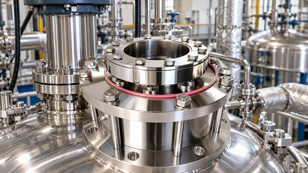
High-temperature reactor seal problems are rarely solved by choosing a heat-resistant face material alone. Heating moves the agitator shaft and vessel structure by different amounts, thermal gradients can distort the gland and seal faces, and inadequate cooling can turn small alignment or lubrication changes into leakage. The design task is to preserve face tracking through the full heat-up, hold, cool-down, and cleaning cycle—not simply to select a seal with a high temperature label.
A reactor seal is mounted where the vessel head, gland, shaft, and drive meet. These parts do not share one temperature or one expansion path. The vessel may heat from the process side while the drive remains cooler; the shaft may conduct heat upward from an immersed agitator; and the seal chamber may be cooled or insulated. As temperature changes, each component grows according to its material, heated length, restraint, and temperature profile.
For a first estimate, free thermal growth is proportional to the component length, its thermal-expansion coefficient, and its temperature change. That relation is a screening aid, not a seal-sizing result: a reactor has gradients, supports, joints, and constraints that change the actual displacement. A long shaft can move axially at the seal even if the seal itself is relatively cool. The relevant input is the measured or engineered relative movement between the rotating assembly and the seal housing over the operating cycle.
Movement can be gradual at steady state but most demanding during transitions. Heat-up, reaction exotherms, steam or hot-fluid changes, vacuum, cooling, and wash cycles can produce different rates of expansion in the vessel and shaft. A seal that runs acceptably after equilibrium is reached may still see a transient face-load change during ramping or shutdown.
When the shaft lengthens relative to the gland, the seal’s compensating elements must follow without reaching the end of their travel. Too much compression can increase face load, frictional heat, and wear; too little can reduce contact stability and permit leakage. Deposits or corrosion can also increase drag on a sliding secondary seal, limiting its ability to follow the shaft.
Do not specify movement as a single unexplained number. Record cold and hot shaft positions, the reference point, direction, operating speed, and whether the value includes runout, vibration, or only thermal travel. Identify any axial float in the drive, thrust bearing, coupling, and agitator. The seal supplier needs to know the movement at the seal—not only the movement measured at a remote bearing.
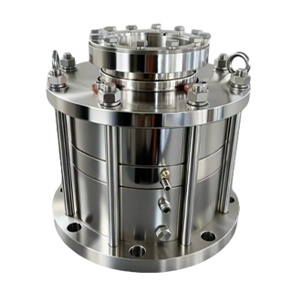
The correct design response depends on the movement pattern and the equipment. A seal arrangement with an appropriate compensation range, flexible element, or floating configuration may accommodate travel differently from a conventional sliding design. Xinyoumi’s reactor portfolio includes configurations for vertical and horizontal vessels, while its published case describes a floating-ring and labyrinth arrangement for one horizontal high-temperature process with substantial axial extension. That case is application-specific; it is not a universal travel rating.
A reactor flange is not necessarily a rigid, isothermal plane. Uneven heating, jacket layout, nozzle geometry, bolt restraint, gasket compression, and thermal gradients through the vessel head can tilt or dish the mounting surface. If the gland follows that movement, the seal may experience angular misalignment or a change in concentricity. This shifts the load distribution around the faces and can create localized heating even where average temperature appears acceptable.
The installation check should go beyond cold alignment. Verify flange flatness and runout, shaft perpendicularity and concentricity, gland fit, bolt tightening sequence, and shaft condition against the applicable specifications. For steep or uneven ramps, consider how the mounting interface behaves hot and during cooldown. Do not compensate for flange distortion by arbitrarily changing spring compression.
The two seal faces generate heat through friction and receive heat from the process, shaft, and surrounding hardware. If heat is removed unevenly across a face or through its thickness, the face can develop a temperature gradient. Because the face ring, carrier, and metal parts expand differently, the nominally flat interface may distort into a slight cone or dish. The direction and magnitude depend on geometry, materials, heat input, cooling path, and restraint; they cannot be inferred from the face material name alone.
Distortion changes the contact pattern. A narrow contact band can raise local heat and wear, while a gap or unstable contact can increase leakage. Thermal distortion may coexist with shaft growth and flange tilt, so replacing the face pair alone can reproduce the failure. Inspect for uneven wear, scoring, discoloration, cracks, deposits, and changes in flatness alongside the operating history.
Face pairing, ring support, balance, secondary seals, and the heat-removal path should be reviewed as one system. Material selection still matters for temperature, compatibility, and wear, but there is no universally best face combination for every reactor. The design basis should state the actual seal-area temperature and thermal transients, not only the batch’s maximum process temperature.
Cooling works only when the utility is available at the required condition and removes the heat load. Low flow, fouling, a closed valve, incorrect connections, vapor lock, or interruption can raise seal-area temperature. This can destabilize the lubricating film, alter fluid properties, age secondary seals, and increase face gradients. Confirm performance through flow, inlet and outlet temperatures, pressure, and alarms.
Rapid cooling can be as important as overheating. If the vessel, shaft, and seal hardware cool at different rates, clearances and axial positions move again. Abrupt temperature changes can also impose thermal stress on brittle face materials or their supports. Review startup, shutdown, cleaning, and emergency utility-loss sequences, and define whether cooling should start before heat-up and continue through cooldown. Follow the seal and equipment manufacturer’s approved operating instructions; do not assume a universal delay or flow setting.
Xinyoumi lists reactor seals and auxiliary equipment. For temperature gradients or long cycles, confirm the arrangement, cooling connections, support medium, instrumentation, and utility-failure response together. Any proposed design still needs to be checked against the vessel drawings and duty.
Give the supplier a complete thermal and movement picture rather than a materials wish list. Include:

Ask the supplier to state its design assumptions, allowable movement range, face-loading approach, thermal basis, cooling requirements, and limits that remain to be verified. If an existing installation is being replaced, compare its original assumptions with current operating data. The product should be assessed as a seal-and-support assembly under the real thermal cycle, not as a catalog part in isolation.
For a reactor-specific review, Xinyoumi’s reactor mechanical seal systems and auxiliary equipment pages provide starting points for the equipment discussion. The company’s published high-temperature reactor case illustrates why axial travel and temperature must be considered together in a particular application.
High-temperature reactor seal reliability depends on managing relative movement and heat flow through the entire cycle. Shaft growth changes the seal’s working position; flange distortion changes alignment; thermal gradients can cone the faces; and failed or poorly controlled cooling can magnify all three. Define the hot and cold geometry, ramp profile, seal-area temperature, and utility behavior before settling on materials or a seal configuration. For an application fit check, contact Xinyoumi’s technical team with equipment drawings, process conditions, movement data, cooling details, and failure history.
Heat-up can move the shaft and vessel by different amounts before temperatures stabilize. The resulting change in seal compression, flange alignment, face temperature, or support-fluid condition may cause transient leakage even if the seal operates at steady state.
No. A suitable material can tolerate a specified temperature and process environment, but thermal gradients and mechanical restraint can still distort a face or its carrier. Face geometry, support, heat transfer, and alignment also matter.
Measure or calculate relative shaft-to-gland movement at the seal across the operating cycle. Record the cold reference, hot position, direction, and whether the reading includes vibration, runout, or drive-system float.
Follow the approved shutdown or contingency procedure. Record seal-area and utility temperatures, flow and pressure, leakage timing, and alarms; inspect for uneven wear or thermal damage before restart. The safe response depends on the seal design and process hazards.